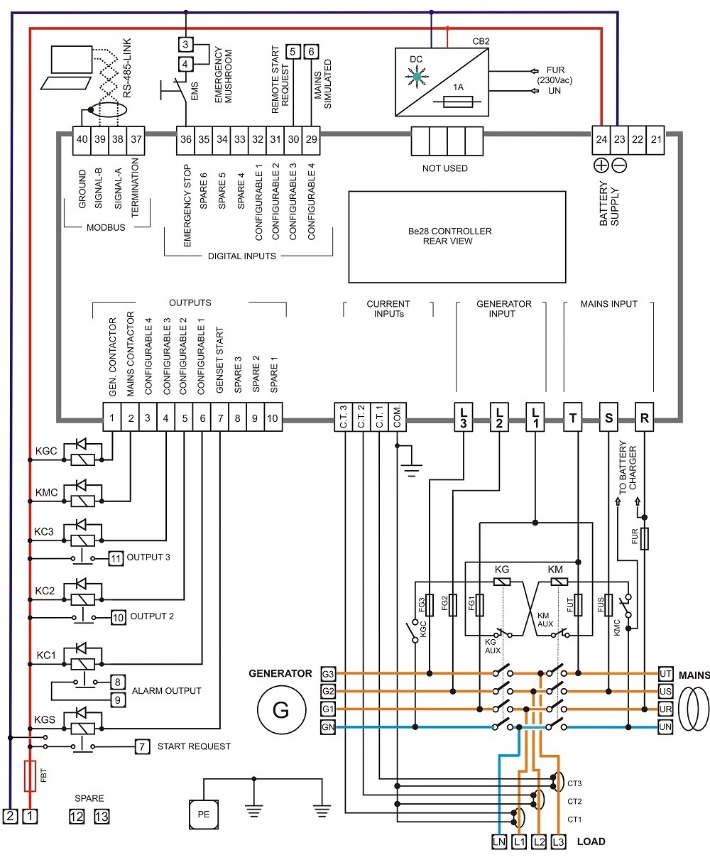
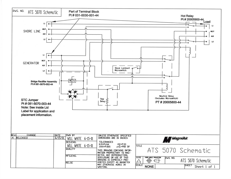
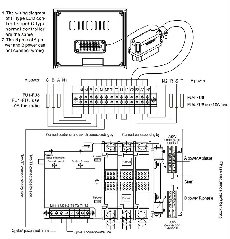
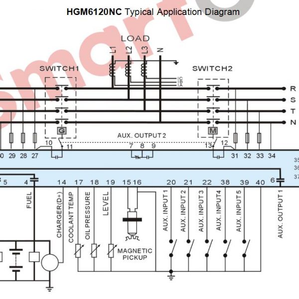
If some conditions are fullfiled d01 and d02 will close and yc of cb1 n if. Wiring diagram sheets detail.

Automatic Transferred Switch Ats Circuit Diagram
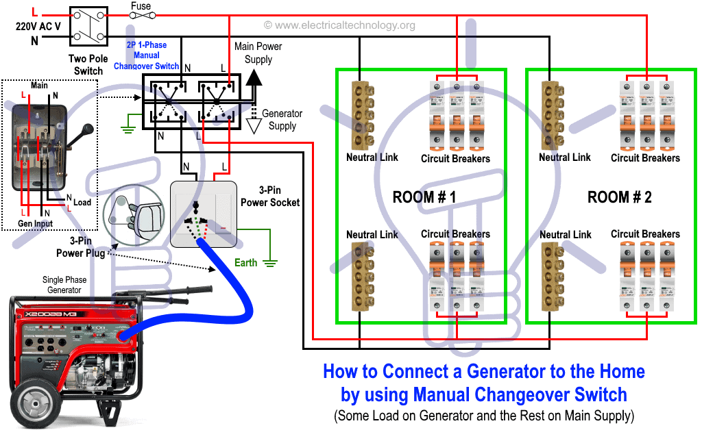
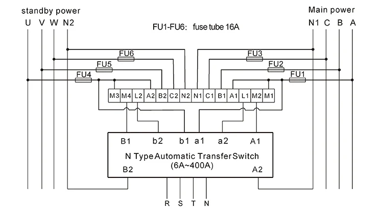
Ats electrical diagram. Here we are talking about automatic transfer switches ats also known as automatic mains failure amf panel to cater uninterrupted power supply from mains or backup sources like. Switches may be manually or automatically operated. Mar 3 2016 automatic transferred switch ats circuit diagram electrical engineering blog. Ats wiring diagram for standby generator generac ats wiring diagram collection generac automatic transfer switch wiring diagram simple design between solargenerator download wiring diagram. Generac 200 amp automatic transfer switch wiring diagram sample generac 100 amp automatic transfer switch wiring diagram elegant 16. Generac 100 amp automatic transfer switch wiring diagram.
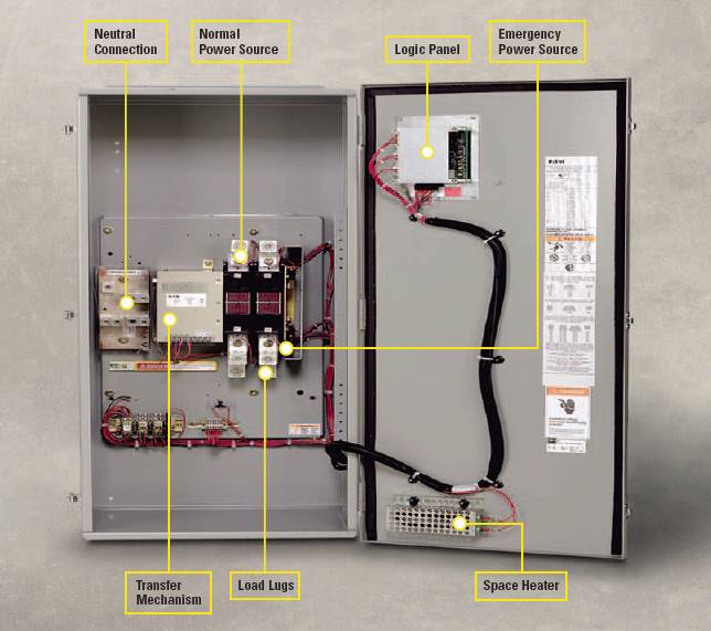
Ats transfer switch automatic transfer switch wiring diagram free rds2 e radin electric provides ats design engineering and full after sales support for a wide range of automatic transfer switch applications. A transfer switch is an electrical switch that reconnects electric power source from its primary source to a standby source. Designed and written by. In addition to the rating and the related electrical breaking specifications the selection criteria are. Generator automatic transfer switch wiring diagram generac with. Installation constraints inside the enclosure glossary cl ncl g q1 q2 ats transformer cl ncl g q1 q2 ats genset cl ncl g q1 q2 ats critical load cl ncl g q1 q2 ats non critical load cl ncl g q1 q2 ats standard diagram.
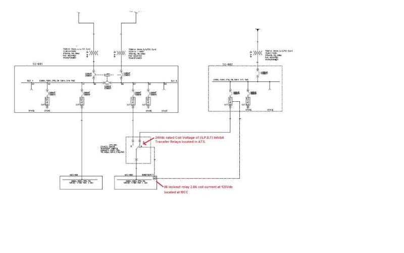
Both circuit breakers are normally closed. Whole house transfer switch wiring diagram awesome 11 plus generator. Hello guys hope that somebody can help me with reading ats schematic. The following article explains an enhanced automatic transfer switch ats circuit which includes several customized sequential changeover relay stages making the system truly smart. An automatic transfer switch ats is often installed where a backup generator is located so that the generator may provide temporary electrical. Reliable electrical power becomes one of the most wanted factor in modern world industry where operation should be uninterruptible and maximize the cycle of operation output quality and to avoid losses and damages.
The load must be able to tolerate the few cycles of interruption while the automatic transfer device operates. The circuit presented here is an ats with following features. Figure 1 shows automatic transfer between two low voltage utility suppliesutility source 1 is the normal power line and utility source 2 is a separate utility supply providing emergency power. So far i know if there is a voltage coming from normal supply via q611 a coil k1 will energised and the voltage will come to x211 on ats.
