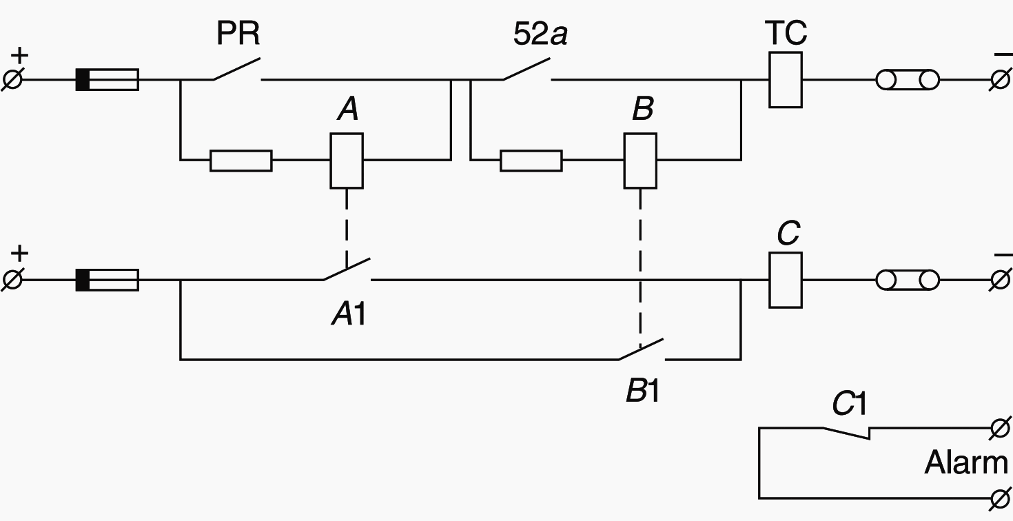
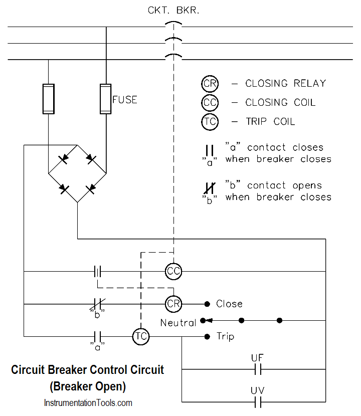
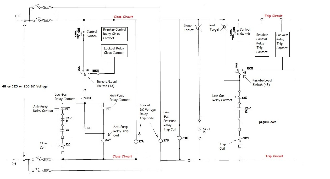
One example of a dc schematic is a circuit breaker control schematic that shows the tripping and closing of the circuit breaker whether from controls or protective devices as well as the alarms for. The symbol for a thermal fuse used in any electrical circuit diagram.

3 Phase Transformer Wiring Diagram Breaker H1 Wiring Diagram
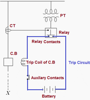
Circuit breaker control circuit diagram. Interpreting common circuit breaker schematic diagrams abb circuit breaker schematic diagram. Quite often it is overwhelming to make sense of the entire scheme at a glance. A thermal fuse is a temperature sensitive switch. It operates on the temperature rather than the current unless the current is sufficient to increase the temperature above the threshold point. We will be using this simple diagram to discuss the components involved with the electrical operating sequence of a circuit breaker. Vacuum circuit breaker in hindi कस कम करत ह हद म duration.
Free electrical education 506427 views 1628. The complete schematic diagram of electronic circuit breaker is given in the image below. A typical wiring diagram with dc control for a westinghouse dhp is shown in the figure below. Read further for the explanation of the same. Ac device that we use in our homes generally have a limit to handle the current and voltagethese threshold voltage and current are called the device rating and are the measurements given by the manufacturers in the range of which the device will work properly. As shown above in circuit breaker schematic it is really simple and just a bunch of resistors capacitors and other stuff.
High capacity off grid solar generator rev 4 wiring diagram parts list design worksheet duration. Electronic circuit breaker circuit diagram working and applications. Aventri event meeting management technology. With an abbite k line circuit breaker the contact marked cps control power switch on the schematic is used to disable the motor charging circuit and would normally be closed. It should be noted that sometimes the control functions are supplied by ac and are included in the elementary diagram refer to figures 6 and 8. Understanding a breaker scheme is important if you plan on designing a substation.
Desert prep recommended for you. The figure below depicting a circuit breaker scheme will be used to explain various elements of the pcbs design and its control. But what actually happens behind all these. A quick look at a typical medium voltage circuit breaker control scheme with an explanation of important components.

