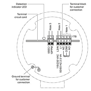
Housing style diagram e page a18 diagram e page a18 diagram e page a18 courtesy of steven engineering inc. It is a universal shaft sensor mount suitable for all industry standard cylindrical 18 and 30 mm or din style inductive sensors including 4bs m100 m300 m800 elite and milli speed sensors.

Cnn Heat Maps Class Activation Mapping Cam Glass Box
Zss connection diagram. 230 ryan way south san francisco ca 94080 6370 main office. 38 mm 15 maximum gap pl 363 4 980715. 10 32 screw 4 places. Thus the zss will not detect the motion of uniform ferromagnetic masses that do not produce pulses within the period of the time delay on zero speed. Maximum acceptable working pressure. Block diagram l6258ex 632 figure 2.
No additional control box needed. Pin connection top view table 3. Proximity type zero speed switchzss rated voltage 12vdc. At the heart of an inductive proximity sensor prox sensor or prox sensor for short is an electronic continue reading basic operating. 650 58 8 9200 outside local area. Used to detect speed of the rotating moving object.
They also conduct heat from die to printed circuit copper. Connection of all control wires. Zs09p zero speed switch sensor is an all in one device that combines sensor and relay. Proximity sensor circuit diagram when target is detected. 6000 psi 414 bar temperature range 45f to 275f 43c to 135c rated fatigue pressure 10 7 cycles per nfpat261 1974. If the metal object called as target as we discussed earlier in this article is moved towards the proximity sensor then the eddy current will increase accordingly.
Pin functions pin name description 1 36 pwrgnd ground connection 1. While the underlying electrical engineering is sophisticated the basic principle of operation is not too hard to understand. The whirligig is a fully guarded target for easy mounting of motion sensors. A high level causes current to. Did you ever wonder how an inductive proximity sensor is able to detect the presence of a metallic target. Connection of the probe should be made via flexible conduit for.
Check all programmable setpoints and adjust as necessary. Be certain that the actual lug torque values are in keeping with the requirements outlined in the instruction book to insure the integrity of power connections. 3000 psi 207 bar. Thus the load on the. In addition adjust any optional accessories as required. 2 17 ph1 ph2 these ttl compatible logic inputs set the direction of current flow through the load.
Due to this load will be caused on the sensor that decreases the electromagnetic field amplitude.


