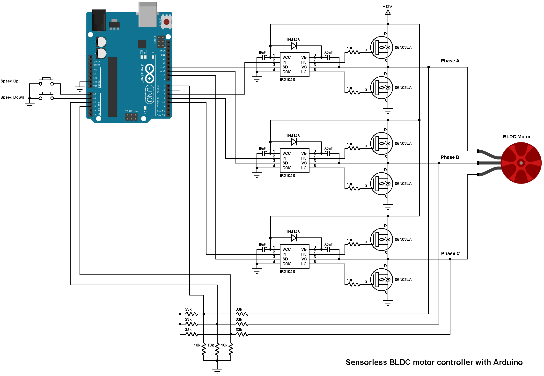
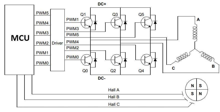
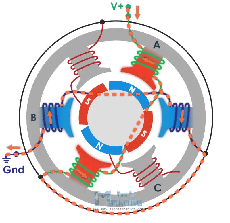
Block diagram of a typical brushless dc motor control or drive system is shown in the following image. It also shows the three phases of the stator armature and rotor with d and q axes indicated therein.

Designing Motor Controls For Robotic Systems Embedded Com
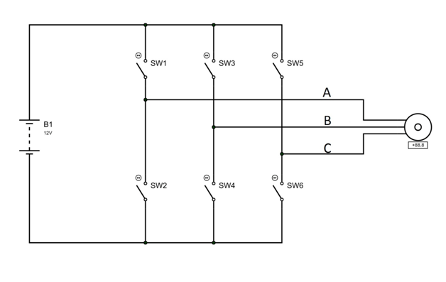
Brushless motor diagram. One common setup is called the full bridge drive circuit. 2018 24v36v48v 250w350w bldc motor speed controller 6 mosfet dual. American tech 68235 views. Diy super brushless motor driver easy way to make a powerful brushless motor driver duration. Lets assume we have a 5055 3000kv brushless outrunner motor. An electric motor develops torque by alternating the polarity of rotating magnets attached to the rotor the rotating part of the machine and stationary magnets on the stator which surrounds the rotor.
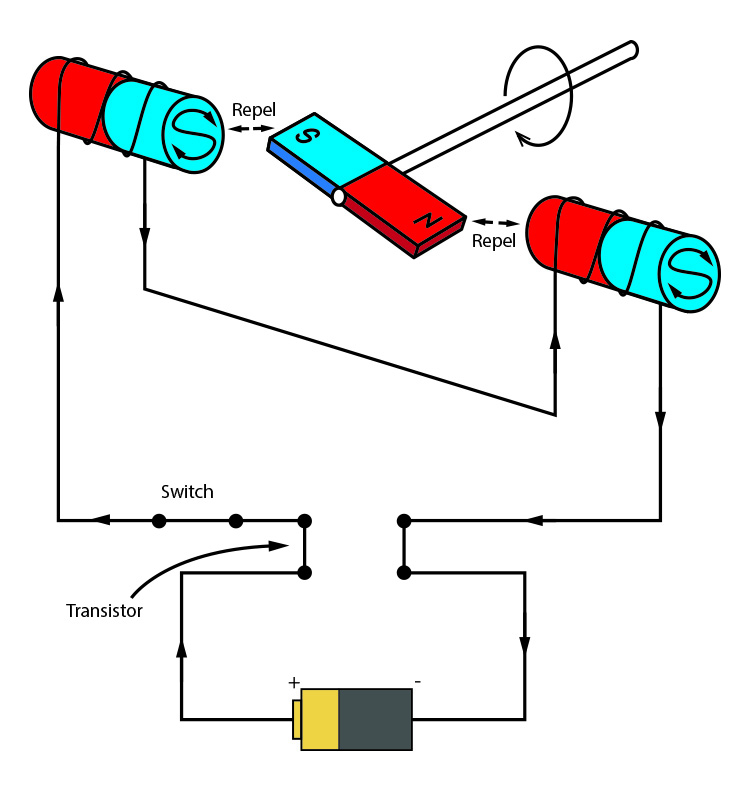
Then you use a computer connected to high power transistors to charge up the electromagnets as the shaft turns. I am learning about control sensorless brushless motor dc 3 phase. Bldc motor controller wiring diagram collections of sensored brushless dc bldc motor control with pic16f877a. The brushless dc bldc motors increasing popularity is due to the use of electronic commutation. May 2 2014 at 0041 its crazy that was me to make it but always fail. You can simulate signal bemf from motor.
Brushed dc motors were invented in the 19th century and are common. 50 55 3000 50 the first two numbers represent the diameter of the motors housing in millimeters. With the advent of cheap computers and power transistors it became possible to turn the motor inside out and eliminate the brushesin a brushless dc motor bldc you put the permanent magnets on the rotor and you move the electromagnets to the stator. This replaces the conventional mechanics comprised of brushes rubbing on the commutator to energize the windings in the armature of a dc motor. Pwm offers precise control over the motors speed and torque. Wiring diagram as well motor controller wiring diagram brushless.
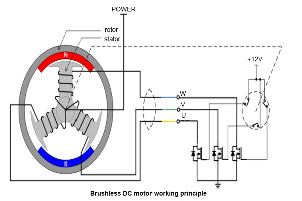
Bldc motor controller wiring diagram. By the way that really purpose and ill take go to make that thing. In this example 50mm 55 the second two numbers represent the length of the. Brushless motors use a standard numbering scheme to describe their physical size and kv rating. The schematic diagram of a brushless dc motor working principle is shown in fig. Brushless dc motors were made possible by the development of solid state electronics in the 1960s.
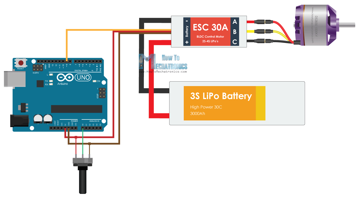
The stator is connected to a variable voltage current source through an inductor and an inverter comprising six scrs s 1 to s 6. A brushless dc motor known as bldc is a permanent magnet synchronous electric motor which is driven by direct current dc electricity and it accomplishes electronically controlled commutation system commutation is the process of producing rotational torque in the motor by changing phase currents through it at appropriate times instead of a. We break the numbers out as follows. This drive circuitry is often known as electronic speed controller system or simply an esc. Diagram drawn using digi key.

