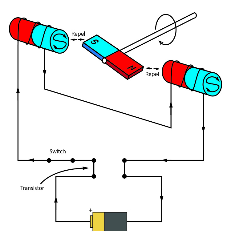
Then you use a computer connected to high power transistors to charge up the electromagnets as the shaft turns. 882 are rectangular pulses ac as shown in the wave forms of fig.

Brushless Dc Motor Ac Motors Electronics Textbook
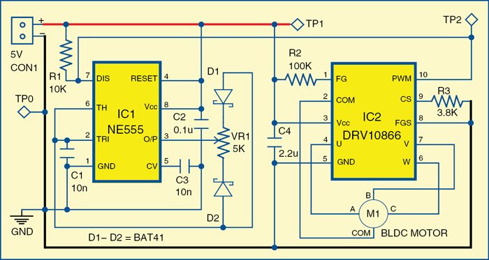
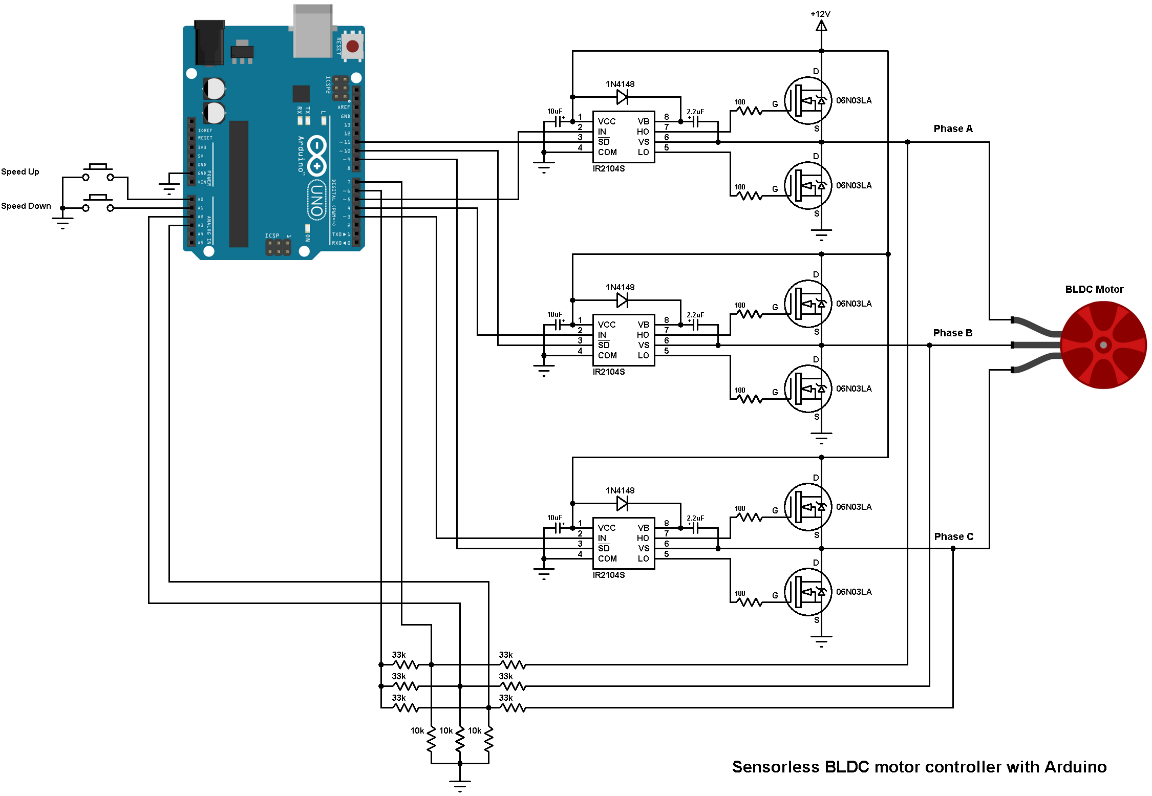
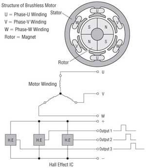
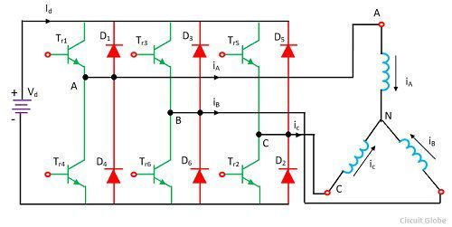
Dc brushless motor diagram. Block diagram of a typical brushless dc motor control or drive system is shown in the following image. Hall effect sensor logic switch output and winding status timing diagram for three. The brushless dc bldc motors increasing popularity is due to the use of electronic commutation. A brushless dc motor known as bldc is a permanent magnet synchronous electric motor which is driven by direct current dc electricity and it accomplishes electronically controlled commutation system commutation is the process of producing rotational torque in the motor by changing phase currents through it at appropriate times instead of a. Brushless dc motor circuit diagram. One common setup is called the full bridge drive circuit.
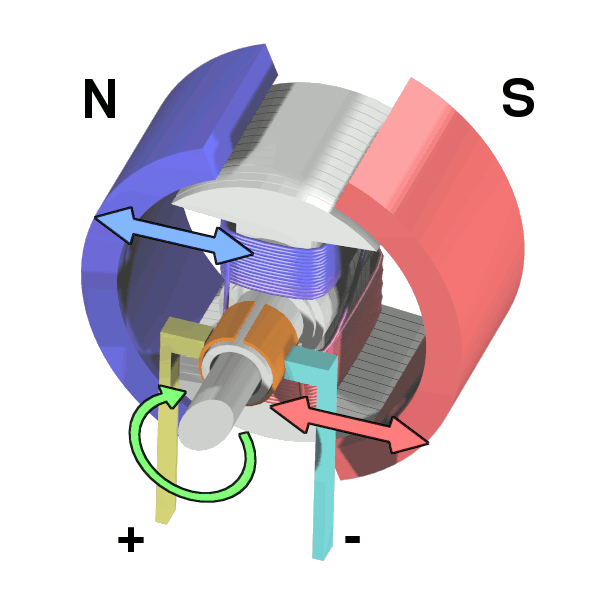
An electric motor develops torque by alternating the polarity of rotating magnets attached to the rotor the rotating part of the machine and stationary magnets on the stator which surrounds the rotor. Currents balanced flowing in the synchronous machine of the brushless dc machine set up of fig. Actual currents are somewhat rounded pulses. This replaces the conventional mechanics comprised of brushes rubbing on the commutator to energize the windings in the armature of a dc motor. Brushless dc motors were made possible by the development of solid state electronics in the 1960s. Brushed dc motors were invented in the 19th century and are common.
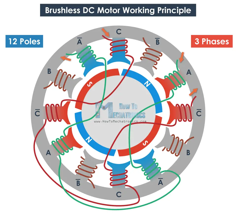
This drive circuitry is often known as electronic speed controller system or simply an esc. Novotny abbas circuit model of a csi fed brushless dc motors is drawn in fig. With the advent of cheap computers and power transistors it became possible to turn the motor inside out and eliminate the brushesin a brushless dc motor bldc you put the permanent magnets on the rotor and you move the electromagnets to the stator.


.png)

