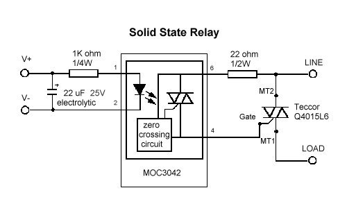
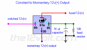
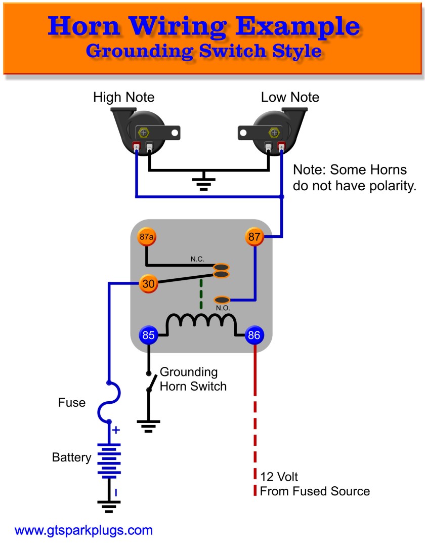
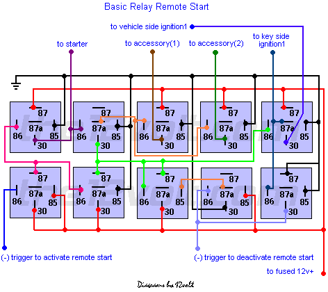
Relay 5 pin wiring diagram duration. Assortment of 12 volt relay wiring diagram.

What Is A Relay Electromechanical Or Electrical Relay
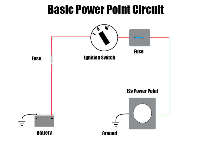
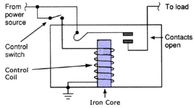
Basic relay wiring diagram. An iron core is surrounded by a control coil. Basic relay diagram iow what goes where. Ajm crews 32812 views. A wiring diagram is a simplified traditional pictorial depiction of an electrical circuit. Obviously therell be more complex looking circuits which will have relays and control units but remember they all operate under the same idea. A typical basic circuit consists of five important parts.
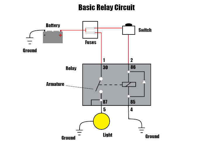
Basic automotive relay operation and simple wiring duration. As shown the power source is given to the electromagnet through a control switch and through contacts to the load. Basic automotive relay operation and simple wiring duration. It reveals the components of the circuit as simplified shapes and also the power and signal connections in between the tools. The following schematic shows the basic circuit. A connection diagram showing what devices go to color coded ports.
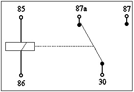
Bosch type relay wiring diagrams. 30 85 87a 87 86 relay logic pink red black orange relay trigger 12v wire to a fused ignition source relay trigger ground wire to a good chassis ground to component basic relay wiring brake switch relay wiring pink red black. How to wire a relay. Basic schematic circuit diagram of relay. Daniel sullivan 811652 views. Computer connection diagram computer connection diagram how to hook up a computer.
The diagram shows an inner section diagram of a relay. How to wire a trailer i will show you basic concepts and color codes for a 4 wire 6 wire and 7 wire connector used for wiring trailers. The transistor allows the hc11 to control the medium sized coil current of relay. Power supply positive from battery fuse. The square relay pinout shows how the relay socket is configured for wiring. Connect the relay with hc11 port pins this is used to control on switches.
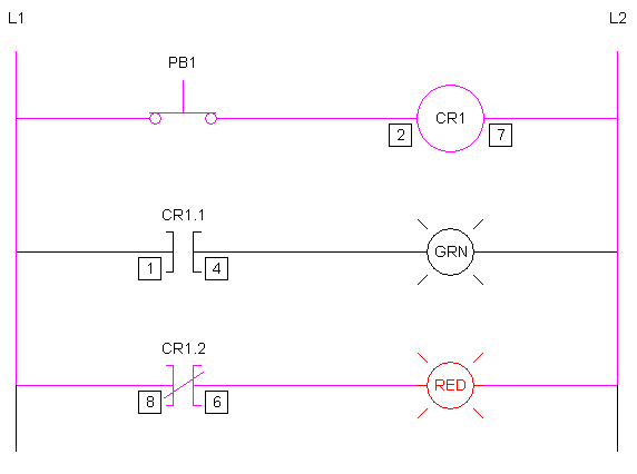
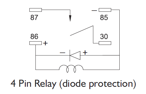
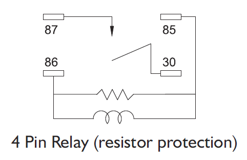
This pinout image is only a 2 pole diagram for room on the page purposes but you can get the picture here with this one since a 3 pole will just have 1 more set of contacts. The diode prevents relay from arcing by giving a return path for the energy stored in the magnetic. The relay function can be better understood by explaining the following diagram given below. Universal relay kit 500479 92965263 instruction sheet rev 60 9192013 this relay kit is designed for muli purpose use. Basic wiring circuit diagram. Diy relay easy step by step electrical.

