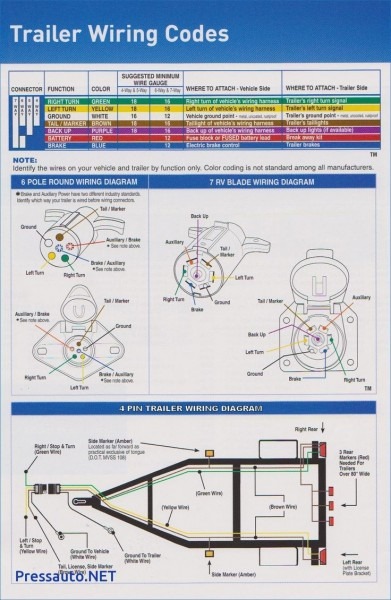
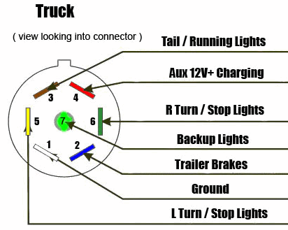
Typically trailer wiring is color coded. 7 pin trailer wiring diagram with brakes.
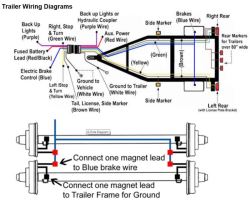
How To Wire Electric Brakes On Gooseneck Trailer Etrailer Com
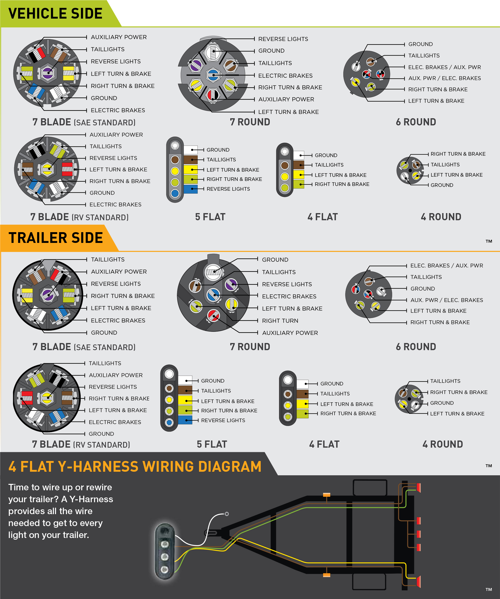
Gooseneck trailer brake wiring diagram. How to setup and use the trailer brakes yukon tahoe suburban silverado duration. 6 way connectors include the basic connection of running lights brake lights turn signals and a ground wire. On most recreational vehicles. Assortment of electric trailer brake wiring schematic. 6 way trailer connectors are often used on gooseneck trailers but can be used for other types such as utility boat trailers and 5th wheels. Complete with a color coded trailer wiring diagram for each plug type this guide walks through various trailer wiring installation solution including custom wiring splice in wiring and replacement wiring.
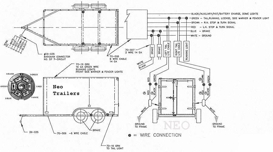
I have attached a drawing that shows how the wiring is typically run for brakes on a trailer. Gooseneck trailer wiring diagram elite gooseneck trailer wiring diagram gooseneck brand trailer wiring diagram gooseneck stock trailer wiring diagram every electric arrangement is made up of various diverse parts. The following trailer wiring diagrams and explanations are a cross between an electrical schematic and wiring on a trailer. How electric trailer brakes work. The other wire from each brake magnet will ground to the trailer frame. If your vehicle is not equipped with a working trailer wiring harness there are a number of different solutions to provide the perfect fit for your specific vehicle.
We recommend these standards because they are pretty universal. 7 way trailer connectors are used by the following vehicle types. Large 5th wheel trailers. Otherwise the arrangement wont work as it ought to be. Danny johnsons garage 82887 views. They also have one wire for trailer brakes and one wire for a battery connection.
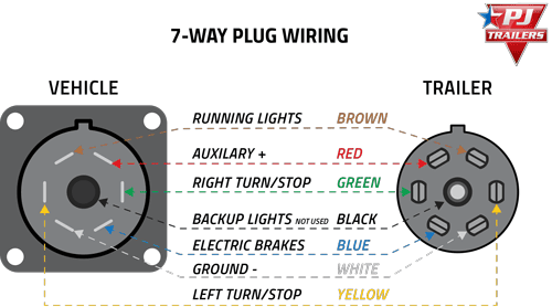
The brake circuit is usually a blue wire which travels to each brake magnet where it is attached to one wire from each brake magnet. A wiring diagram is a streamlined conventional pictorial representation of an electric circuit. Trailer wiring diagrams trailer wiring connectors various connectors are available from four to seven pins that allow for the transfer of power for the lighting as well as auxiliary functions such as an electric trailer brake controller backup lights or a 12v power supply for a winch or interior trailer lights. It reveals the parts of the circuit as streamlined forms as well as the power and signal connections in between the gadgets. 7 way trailer wiring diagram is explained in details in the picture and the table below. Each part should be placed and linked to different parts in specific way.
That said for specific situations there are industrial standards with different connectors and wire arrangements.

