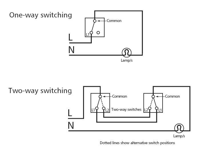
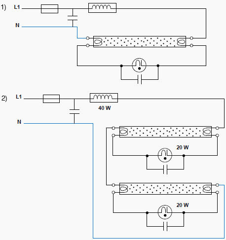
This diagram illustrates wiring for one switch to control 2 or more lights. Phase neutral and groundall three conductors reach to the terminal point of each luminaire and if it has a metal chassis the ground should be connected in the appropriate position.

Products Ced Norfolk Industrial Solutions Network
Industrial lighting wiring diagram. We have and extensive collection of common lighting arrangements with detailed lighting circuit diagrams light wiring diagrams and a breakdown of all the components used in lighting circuits. Light wiring diagram if you need to know how to fix or modify a lighting circuit youre in the right place. The hot and neutral terminals on each fixture are spliced with a pigtail to the circuit wires which then continue on to the next light. These high voltages are stepped down to a low voltage using step down transformers. Multiple light wiring diagram. The contactor contains large load contacts that are intend to handle large amount of current.
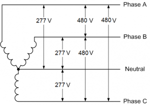
Electrical lines which include lighting circuits begin from the main distribution panel of the installation and each line contains three conductors. This includes schools offices hospitals shopping centers and prisons. Paths of egress must be illuminated by emergency signs and pathway lights. Introduction to lighting circuits. This type of diagram is like taking a photograph of the parts and wires all connected up. The first reason this is bad is on safety grounds.
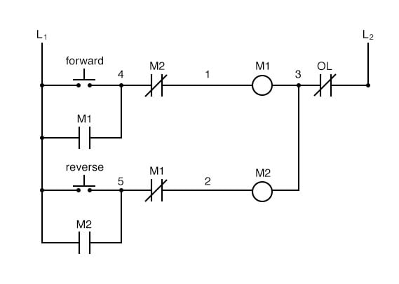
Many people can read and understand schematics known as label or line diagrams. Exit and emergency lighting is required by the united states in all commercial industrial and architectural environments. Say we are working on the light upstairs so we turn off the upstairs lighting circuit thinking we are safewrongthe live is picked up downstairs and there are still live conductors feeding the switch upstairs and if someone flipped the downstairs switch in this diagram that live feed would extend all the way to the lamp too youre fried. This is a start stop push button control schematic which includes contactor m overload relay control transformer and push buttons. Product overview the nlight npp16 family of power packs is the workhorse of an nlight system delivering robust system performance and design versatility for commercial and industrial lighting following above wiring diagram connect wires to line voltage feeds neutrals and loadthe future is here with nlight airn light wiring. Keep your diagram nearby.
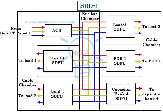
The wiring diagram for connecting thee phase motor to the supply along with control wiring is shown in figure below. Structure of power distribution in industries. The source is at sw1 and 2 wire cable runs from there to the fixtures. Wiring diagrams can be helpful in many ways including illustrated wire colors showing where different elements of your project go using electrical symbols and showing what wire goes where. Wiring diagrams help technicians to see how the controls are wired to the system. In an industrial electric power system electric power is supplied from either private utilities or public utilities or boththe supplied voltage is in the range of 11kv 33kv 66kv or 132kv.
This is why a good diagram is important for wiring your home accurately and according to electrical codes.
