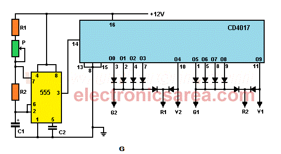
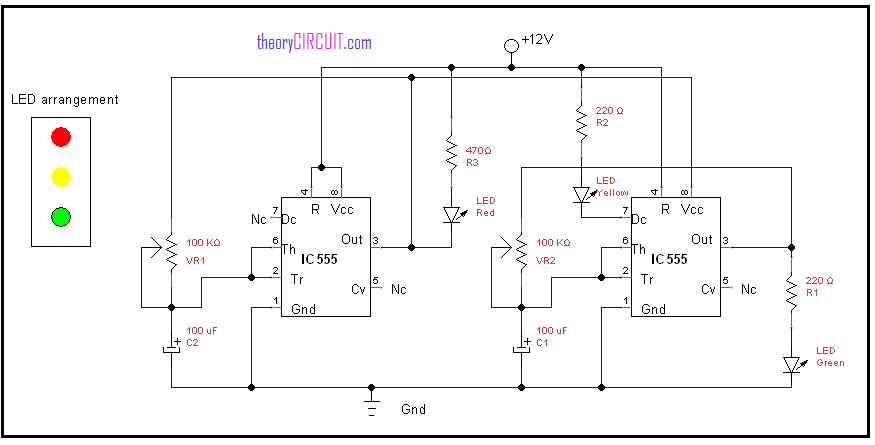
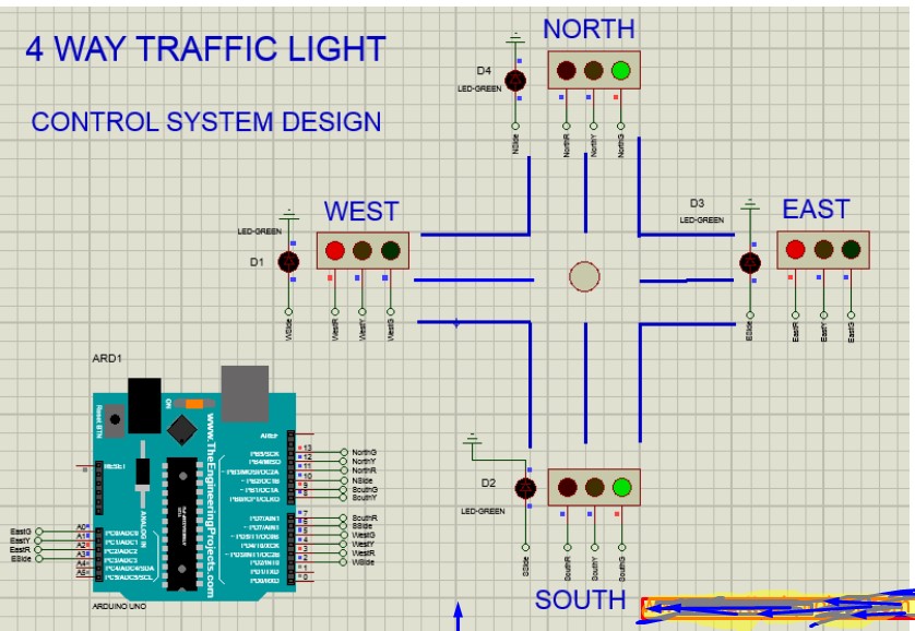
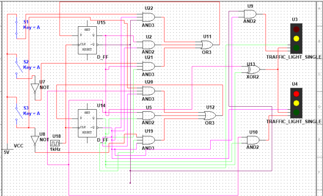
Four way traffic light circuit diagram using 555 timer ic is shown in the above diagram. This traffic light controller will be used to control the flow of traffic.

Control Unit Of A Four Way Traffic Controller Download
4 way traffic light circuit diagram. This is the wiring for a dimmer in a 4 way circuit. How to build an arduino traffic light controller 4 way. This is not the real time traffic light controller. Pin diagram features circuit working with applications. The timer here generates pulses of time period 100ms approximately. There are total of 12 leds used in this project.
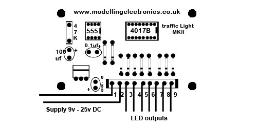
Our traffic light control circuit allows you to bring more realism to your model railway layout or model town. Plc based 4 way traffic light control system x plc practice questions plc tutorials explain what the following plc practice questions on ladder logic circuit does and identify the meaning of each symbol in the diagram. Each signal has 3 leds red yellow and. Three wire cable runs between all the switches and 2 wire cable runs to the light. Cheng low electronic diy. To make this circuit work a 3 way dimmer can be used in place of one or both of the standard 3 way switches.
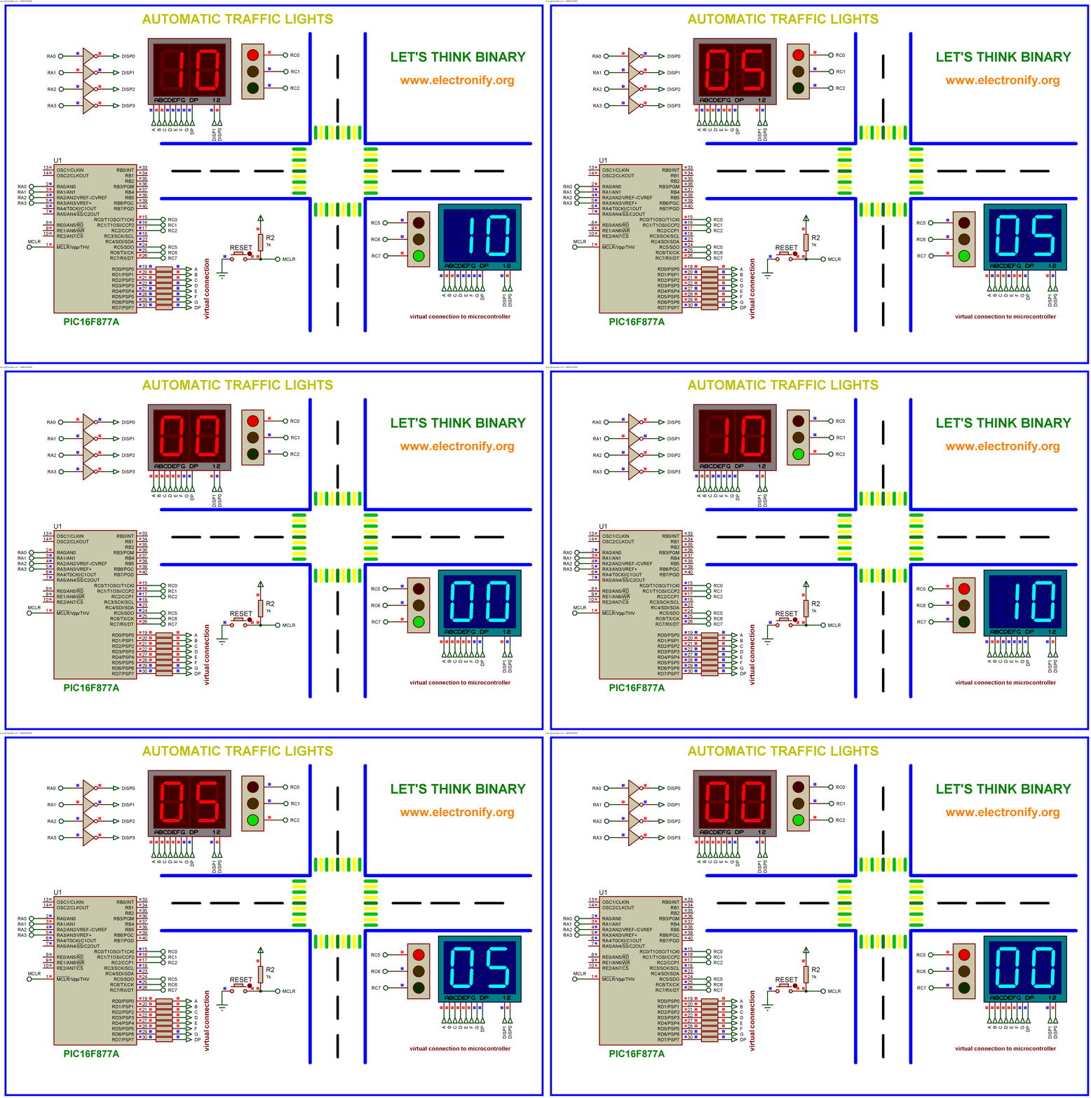
We know each traffic signal light setup will have three colors and representing red for stop yellow for wait and green for go those signals are works based on time intervals. The circuit allows you to control 2 or 4 way traffic allowing for two traffic lights north and south or four traffic lights north south east and west. The first four way three color traffic light was created by police officer william. Circuit diagram for arduino traffic light controller. This project is done to give you an idea of how the traffic light controller works. So at the start the green light of signal 1 and red.
4 way traffic lights diagram. Main circuit diagram of traffic controller. Click image to enlarge. 4 way dimmer switch wiring diagram. In4007 diodes 8 pieces circuit diagram and explanation. Traffic signal lights are very important to regulate vehicles and traffic on roads simple four way traffic light circuit is designed with timer ic 555 and counter ic cd4017.
These can be applied at high traffic areas to avoid traffic blocks or accidents. Traffic light has proved to be an amazing way to stop the vehicular collisions and control the traffic jams in todays modern era where everyone owns the different types of vehicles. Potts in detroit michigan in 1920. Red led 4 pieces blue led 4 pieces and yellow led 4 pieces cd4017 decade counter ic. Circuit diagram of traffic light control mini project. There are two options for purchasing this circuit.
These can be applied at high traffic areas to avoid traffic block. This traffic light controller will be used to control the flow of traffic. This article discusses an overview of what is an lm3914 ic pin configuration features alarm driver circuit using lm3914 and its lm3914 applications.


