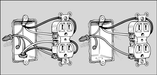
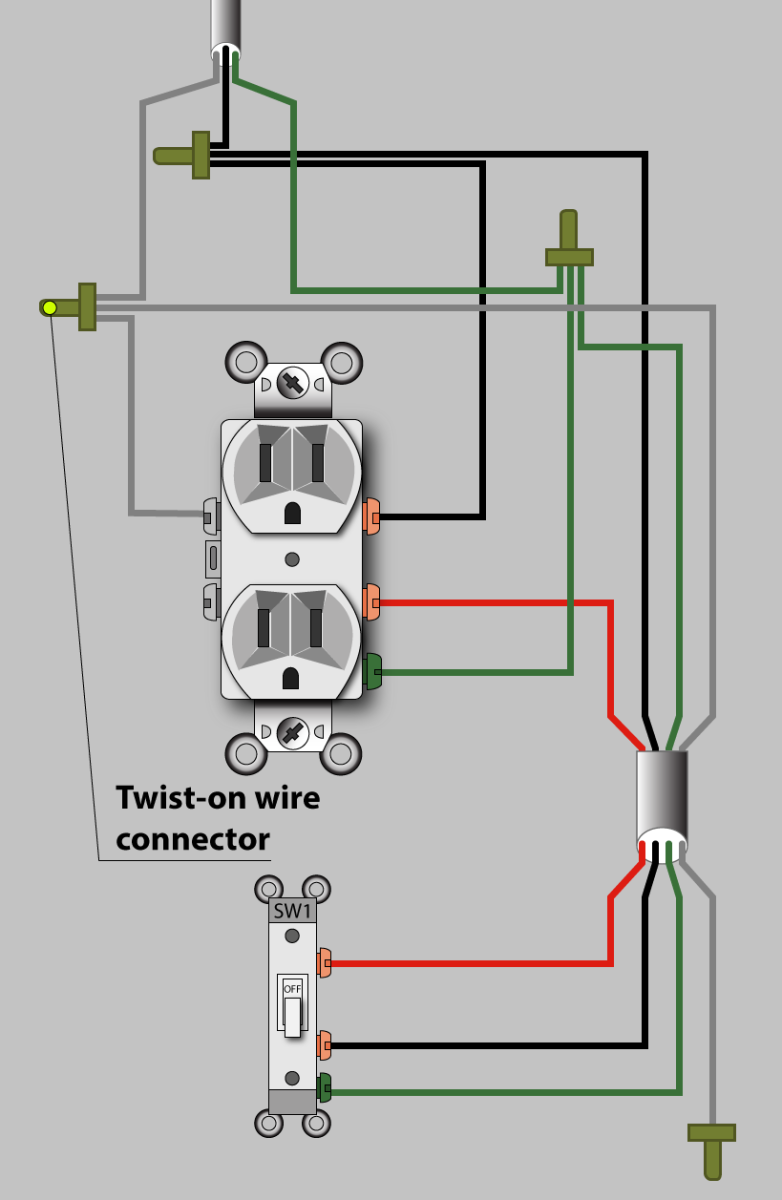
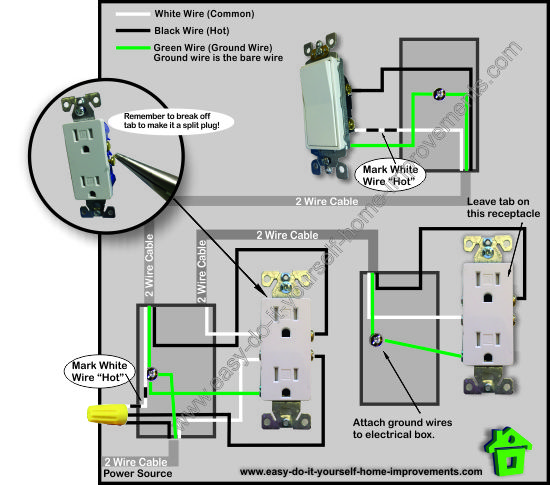
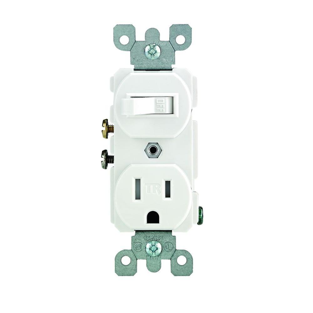
The diagram below shows the power entering the circuit at the grounded outlet box location then sending power up to the switch and a switched leg back down to the outlet. This wiring is commonly used in a 20 amp kitchen circuit where two appliance feeds are needed such as for a refrigerator and a microwave in the same location.
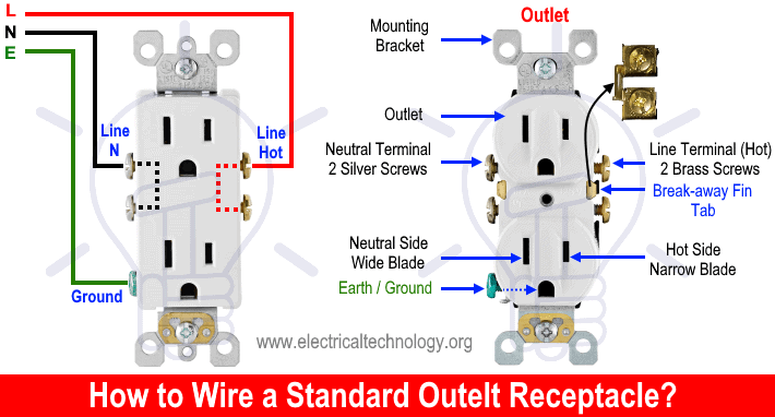
How To Wire An Outlet Receptacle Socket Outlet Wiring Diagrams
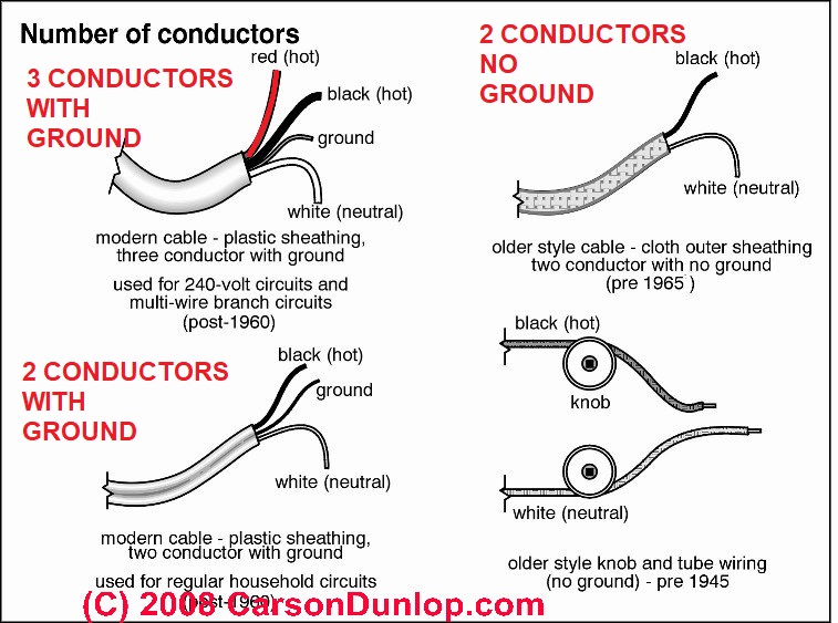
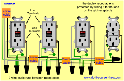
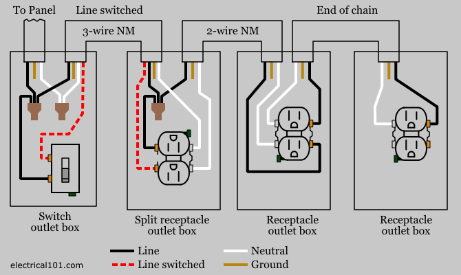
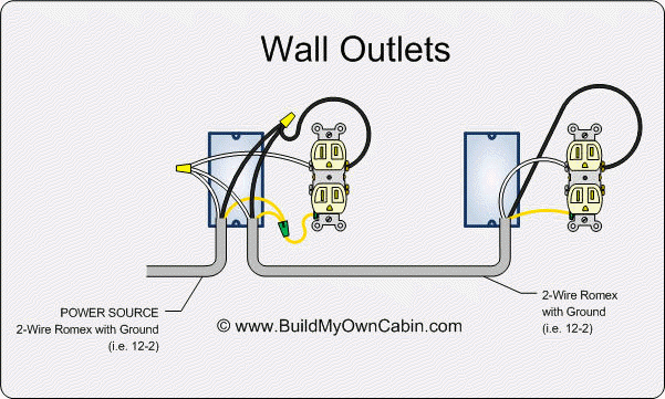
Wiring electrical outlet diagram. An outlet receptacle where one or more receptacle are installed or a supply contact device installed at the outlet to connect an electrical load through plugs and switches. In the diagram below a 2 wire nm cable supplies line voltage from the electrical panel to the first receptacle outlet box. Here 3 wire cable is run from a double pole circuit breaker providing an independent 120 volts to two sets of multiple outlets. In this gfci outlet wiring and installation diagram the combo switch outlet spst single way switch and ordinary outlet is connected to the load side of gfci. With this wiring both the black and white wires are used to carry 120 volts each and the white wire is wrapped with electrical tape to label it hot. The black wire line and white neutral connect to the receptacle terminals and another 2 wire nm that travels to the next receptacle.
And second its easier to press the outlet back into the box if fewer of its screws are connected to wires. This is how to rough in electrical wiring yourself. Box typical inside dimensions are about 2 in. The outlet addition methods we show here are based on the most common wiring 14 gauge wire on a 15 amp circuit and an 18 cu in. This outlet is commonly used for a heavy load such as a large air conditioner. Wiring a 20 amp 240 volt appliance receptacle.
Wiring a gfci outlet with combo switch outlet receptacle light switch. Steps to take when wiring the electrical outletreceptacle. The outlet should be wired to a dedicated 20 amp240 volt circuit breaker in the service panel using 122 awg cable. The single pole switch has a neutral conductor for future electronic controls such as a timer or a wifi switch. The neutral wire from the circuit is shared by both sets. How to wire an electrical outlet wiring diagram wiring an electrical outlet receptacle is quite an easy jobif you are fixing more than one outlet the wiring can be done in parallel or in series.
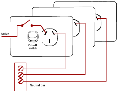
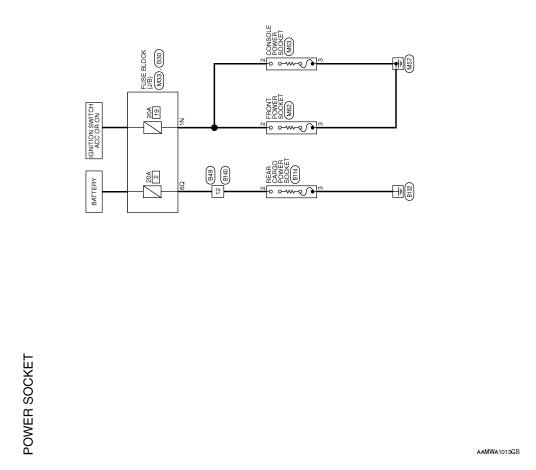
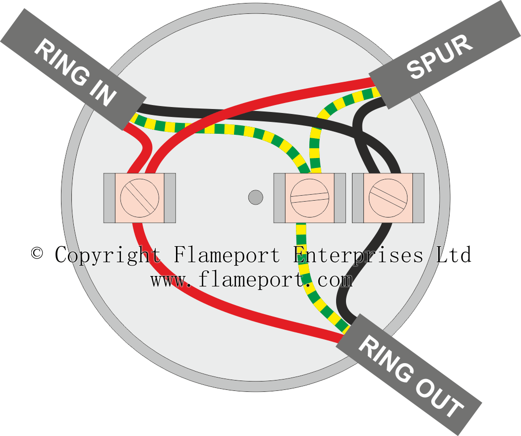
These electrical wiring diagrams show typical connections. This repeats until the end of the chain. According to nec an outlet is the points in an electrical wiring system where current can be taken and utilize by electrical appliances and equipment by plugging them in it. Wiring diagram for dual outlets. Instead use wire connectors to connect the neutral hot and ground wires along with 6 in long pigtails then connect the pigtails to the outlet. Wiring diagram of a switched electrical receptacle outlet and an unswitched electrical receptacle outlet with the power entering the switched outlet electrical box from the circuit breaker panel.




/cdn.vox-cdn.com/uploads/chorus_asset/file/19499872/01_outlet_terms.jpg)


