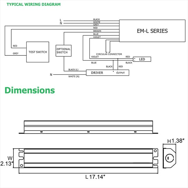
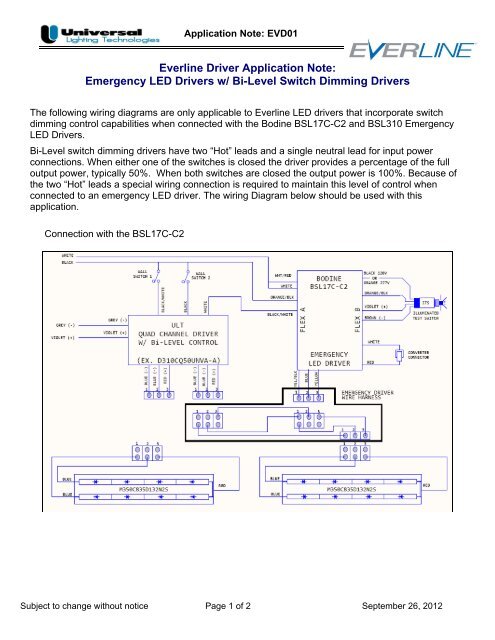
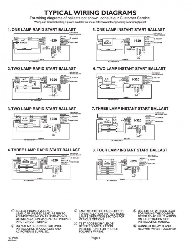
The emergency ballast wiring guide this document has been customized to contain a wide library of individual dia grams for various installation applications. Bodine b90 emergency ballast wiring diagram.

T8 Emergency Ballast Wiring Diagram Diagram Base Website
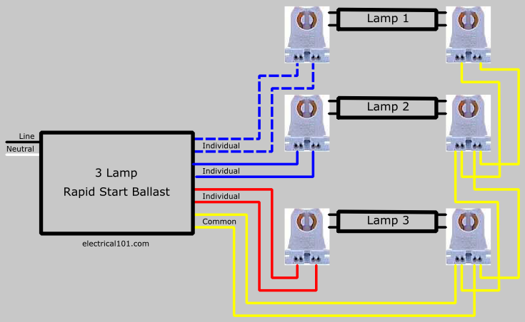
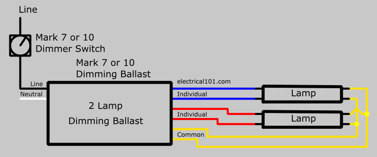
Emergency ballast wiring schematic. Series ballast lampholder wiring 2 and 4 lamps. Fig 104 two 2 lamp instant start ballast wiring diagrams for 2 lamp emergency operation 2 4 17 40 w lamps only wiring diagram for 1 lamp emergency operation emergency ballast and ac ballast must be fed from the same branch circuit typical schematics only. If a diagram cannot be found within this selection consult customer service. The standard ballast has a wiring diagram on it but an emergency ballast has many possible diagrams that are. Series ballast lampholder wiring 3. Some electricians really struggle with them and replace the whole fixture rather than try to figure out where the problem is.
Wiring layouts are comprised of 2 points. A wiring diagram is a streamlined traditional photographic representation of an electric circuit. It shows the components of the circuit as simplified forms and the power and signal links in between the devices. Variety of bodine b90 emergency ballast wiring diagram. The diagrams are categorized primarily according to the number of lamps in the. Parallel ballast lampholder wiring.
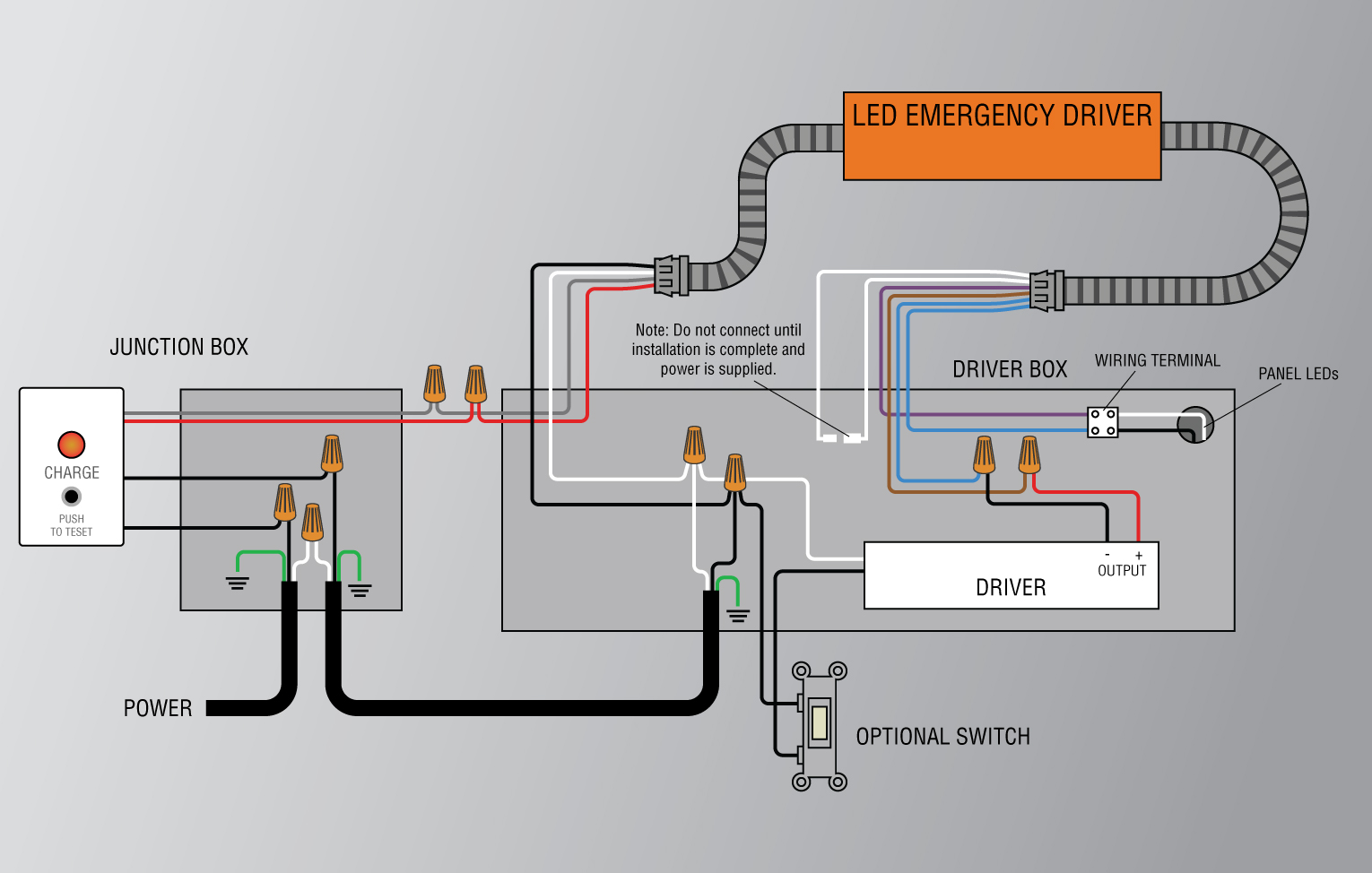
If a diagram cannot be found within this selection consult customer service. A wiring diagram is a sort of schematic which makes use of abstract photographic symbols to show all the affiliations of parts in a system. Another option is to install an led emergency kit that contains all the components to convert the fixture often non led into an emergency lighting system. A wiring diagram is a streamlined standard photographic representation of an electrical circuit. Series ballast wiring 4 lamps. May be used with other ballasts.
Lithonia emergency ballast wiring diagram gallery collections of wiring diagram for emergency lighting new emergency exit lights. Collection of fluorescent emergency ballast wiring diagram. The emergency ballast wiring guide this document has been customized to contain a wide library of individual dia grams for various installation applications. This differs a schematic representation where the arrangement of the parts affiliations on the diagram usually does not represent the components physical areas in the ended up gadget. It reveals the components of the circuit as simplified shapes and the power and also signal connections between the tools. For existing led fixtures an led emergency ballast can be installed to work in conjunction with the led driver so that the fixture will operate in emergency mode.
Series ballast wiring 1 to 3 lamps. The diagrams are categorized primarily according to the number of lamps in the. Signs that represent the elements in the circuit and lines that represent the connections between them. Emergency ballast wiring can be very complex and difficult to troubleshoot.
