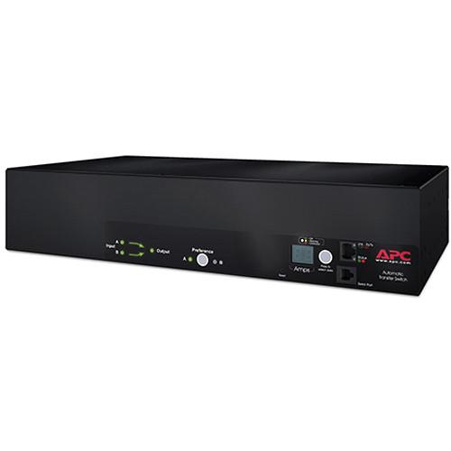
Switch and the tungsten load does not exceed 30 percent of the switch rating. An automatic transfer switch ats for a single phase power generator has been designed to enable the automatic operation and transfer of power supply between a public utility supply and a power.

Gy 8353 Phase Motor Wiring Diagram Pdf Furthermore Ac Motor
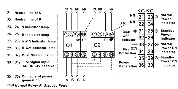
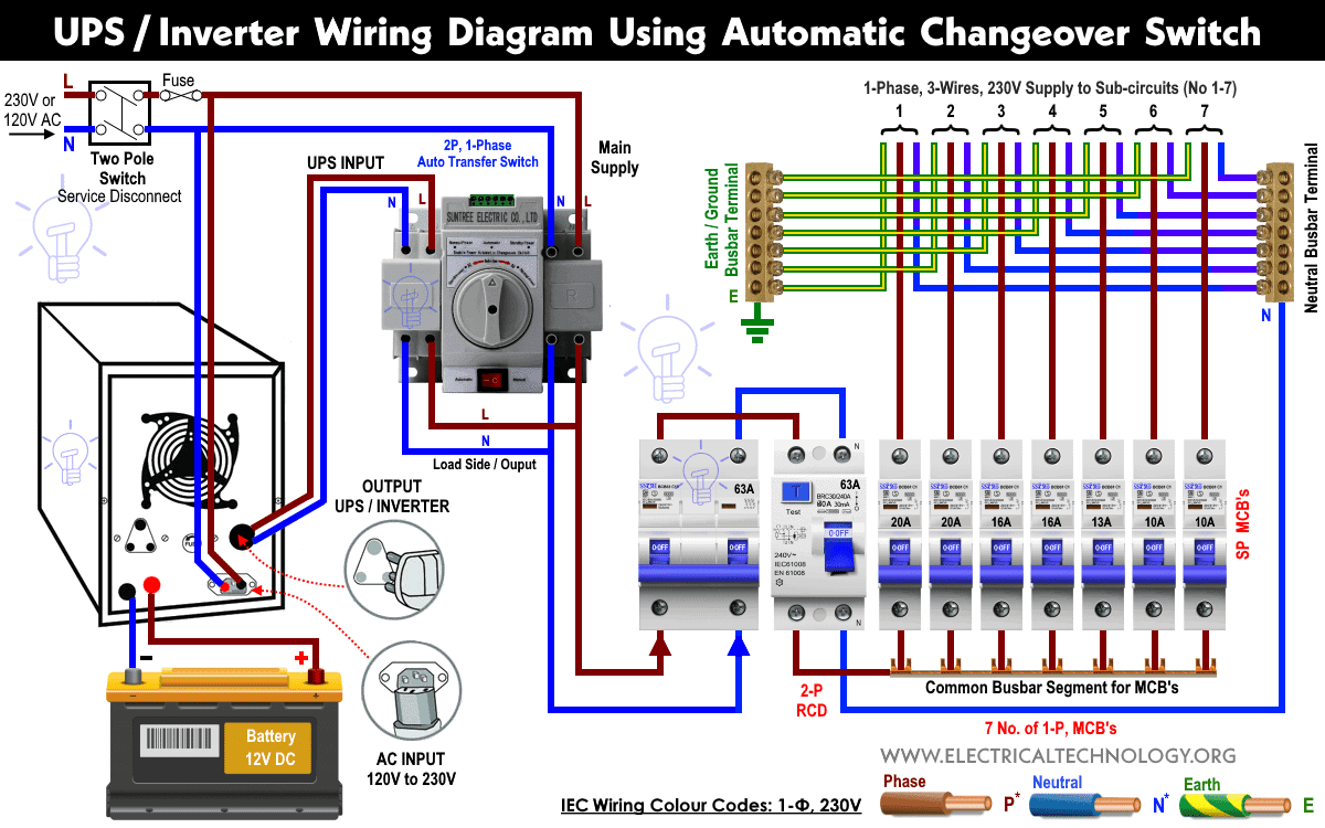
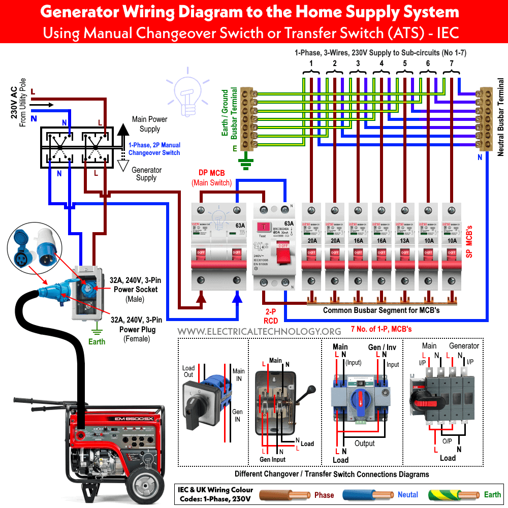
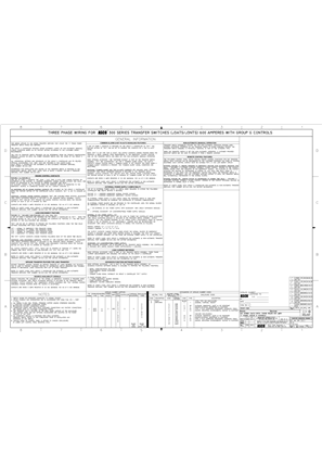
Automatic transfer switch diagram pdf. It is also shows the working and operation for different changeover switches wiring connections like single phase manual changeover switch with generator three phase manual transfer switch connection with generator as well as single phase and three phase automatic transfer switches connections to the 1 and 3 phase generators and main fuse board. Standard diagrams transfer between 3 sources 2 bus bars continued implementation compacity built in solution plug and play mechanical and electrical interlocking are in build operation only 2 or 3 emergency handles instead of 4 or 5 a motorized switch can be added on the non critical loads for optional disconnection. 005036 0 100 amp 250 volts and 004945 1 200 amp 250 volts. 12 selection the size of automatic transfer switch 13 automatic transfer switch components 14 modes of operation 15 schematic circuit diagram for automatic transfer switch 16 recommended cable size 17 specifications 171 general specification 172 controller specification 18 ordering information 19 detailed drawings. This transfer switch is suitable for use on a circuit capable of 22000 rms 200a and 10000 100a symmetrical amperes 240 vac maximum. This ul listed transfer switch is for use in optional standby sys tems only nec article 702.
Automatic transfer switch owners manual ats service entrance hs type transfer switch models.

