We help you compare features and prices for 40 popular boards both microcontrollers and single board computers. Quadcopter can accept load disturbance up to 250g during it hover condition.
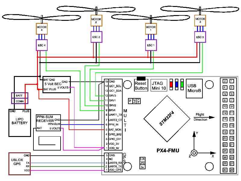
Archived Installing The Px4fmu On A Quadcopter Copter
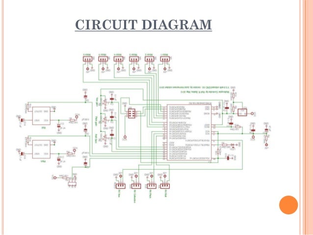
Quadcopter control board circuit diagram. Using this data it then controls the speed of the motors to make the craft move as instructed. From arduino uno microcontroller board used to control quadcopter propellers. All the information regarding the parts that are used in building a quadcopter is provided in this document. Quadcopter dynamics simulation and control introduction a helicopter is a flying vehicle which uses rapidly spinning rotors to push air downwards thus creating a thrust force keeping the helicopter aloft. 1 key figures 2 messages 4 management team 5 review of operations 21 financial review 79 board of directors 85 governance 90 generating transmission and distribution. Altitude roll yaw and pitch.
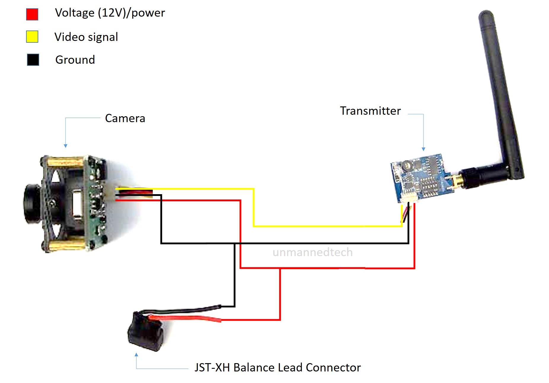
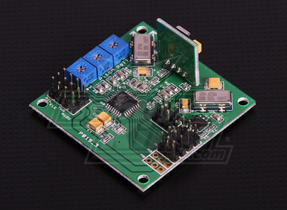
Typically the arduino board is used for these adjustments autonomously. 27 05 remote control helicopter circuit diagram. The flight controller aka fc is the brain of the aircraft. These can be arranged as two coplanar rotors both providing upwards thrust but. Circuit diagram of quadcopter pdfcircuit diagram of remote control helicopter. Fpv quadcopter wiring diagram.
Drone circuit board pdf. Quad rotor helicopter with an on board surveillance camera spy copter a quad rotor with an on board surveillance camera. Check above diagram which show you a sample fpv quadcopter and some parts. Gui is designed using visual basic 2008 express as interface between control base and quadcopter. Designing a practical quadcopter. Transmitter receiver flight controller fpv camera fpv transmitter and antenna fpv receiver and monitor or goggles.
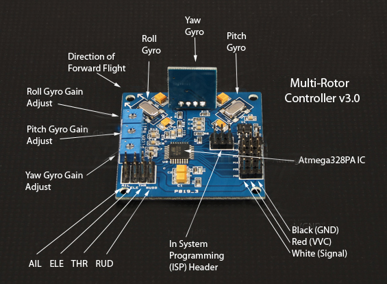
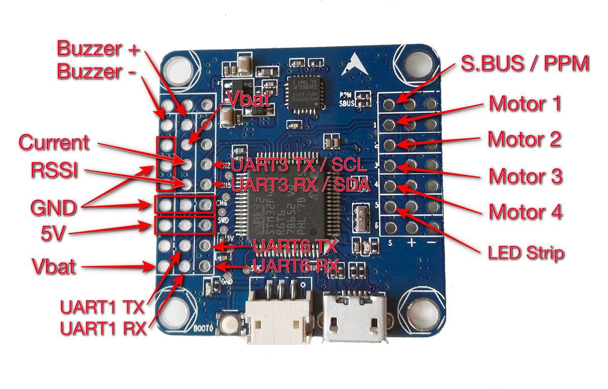
This is achieved by means of a 6 channel radio control transmitter and receiver. Circuit diagram shows how different components are connected to the arduimu board. Since the quadcopter is an unmanned aerial drone transmission of signals takes place wirelessly via radio frequency transmission system rfts. Conventional helicopters have two rotors. Its a circuit board with a range of sensors that detect movement of the drone as well as user commands. 36 schematic diagram and pcb layout 20 37 quadcopter.
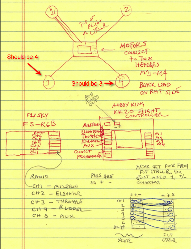
It just needs to be practiced until the full control of the quadcopter becomes achievable and mastered by the user. 343 block diagram of quadcopter altitude closed loop control 40 344 wireless camera 40 345 wireless camera receiver 41. So far we learned about the basic construction of the drone body and hardware now lets learn how to make a quadcopter or a drone circuit quickly and cheaply using very ordinary components. The thrust each rotor produces allows the quadcopter to perform four types of movements. The four bldc motors are mounted on the ends of the quad frame each connected to the flight control board. Remote control drones x6 rc quadcopter 4ch rc helicopter with camera and light big size spy.
The experiment shows that quadcopter can hover with maintain it balancing and stability. Simplest quadcopter drone circuit. You can also add different sensors to your arduino to make your quadcopter more self controlling for example barometer gps sonar etc.

