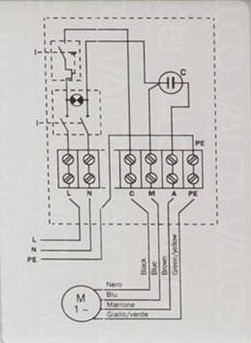
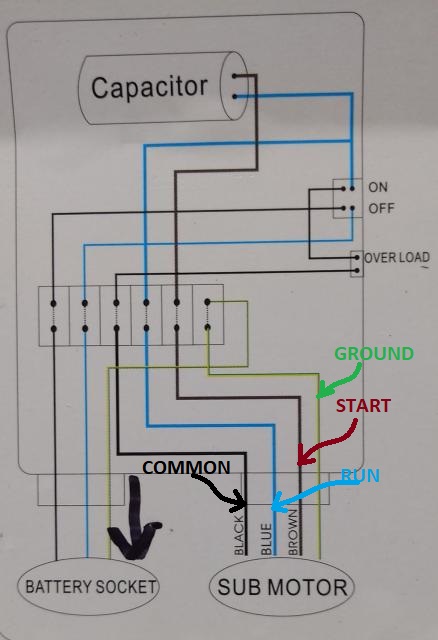
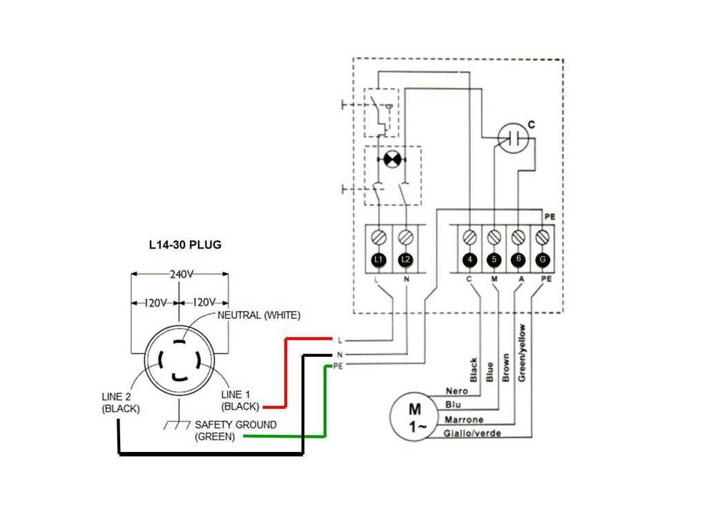
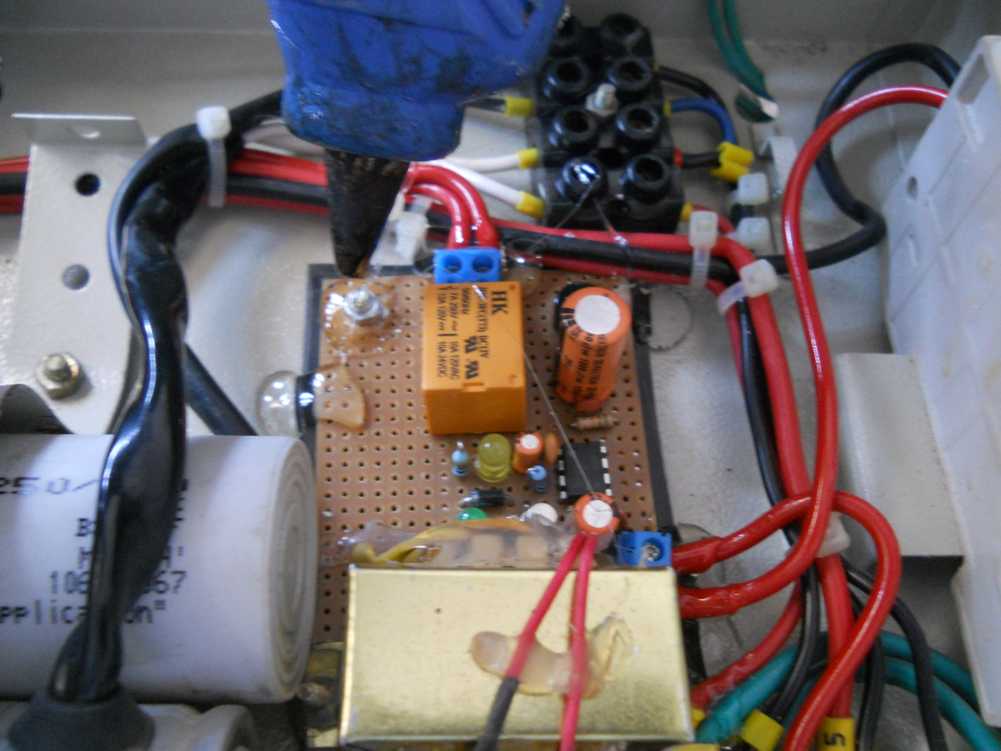
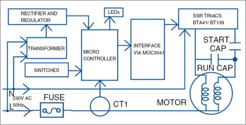
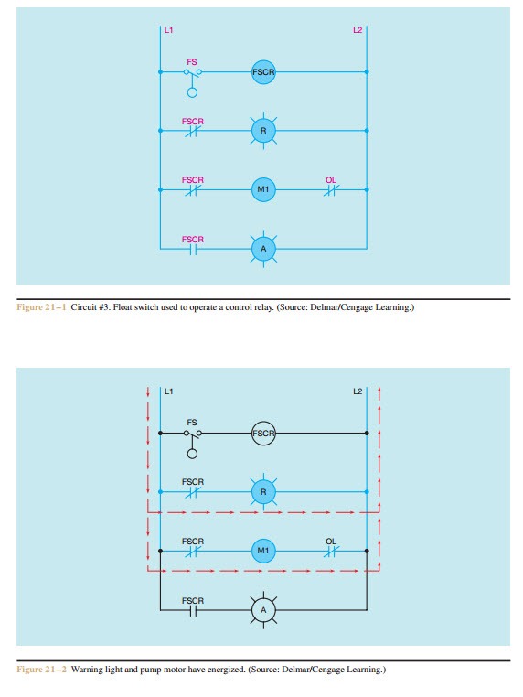
Assortment of single phase submersible pump starter wiring diagram. Three phase submersible pump wiring diagram with straight star nonlinear starter the oncoming supply goes to the mccb circuit breaker.
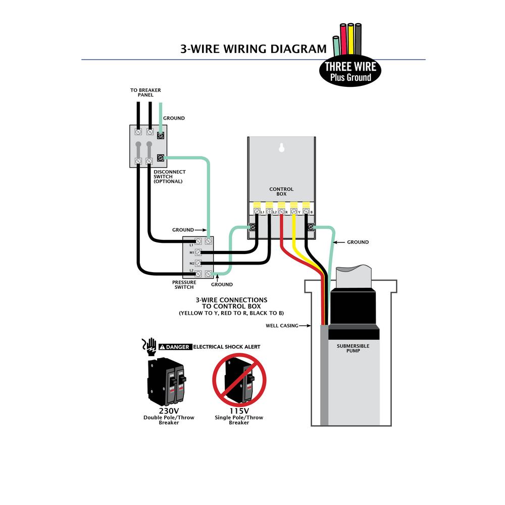
Eco Flo 1 Hp Control Box For 4 In Well Pump
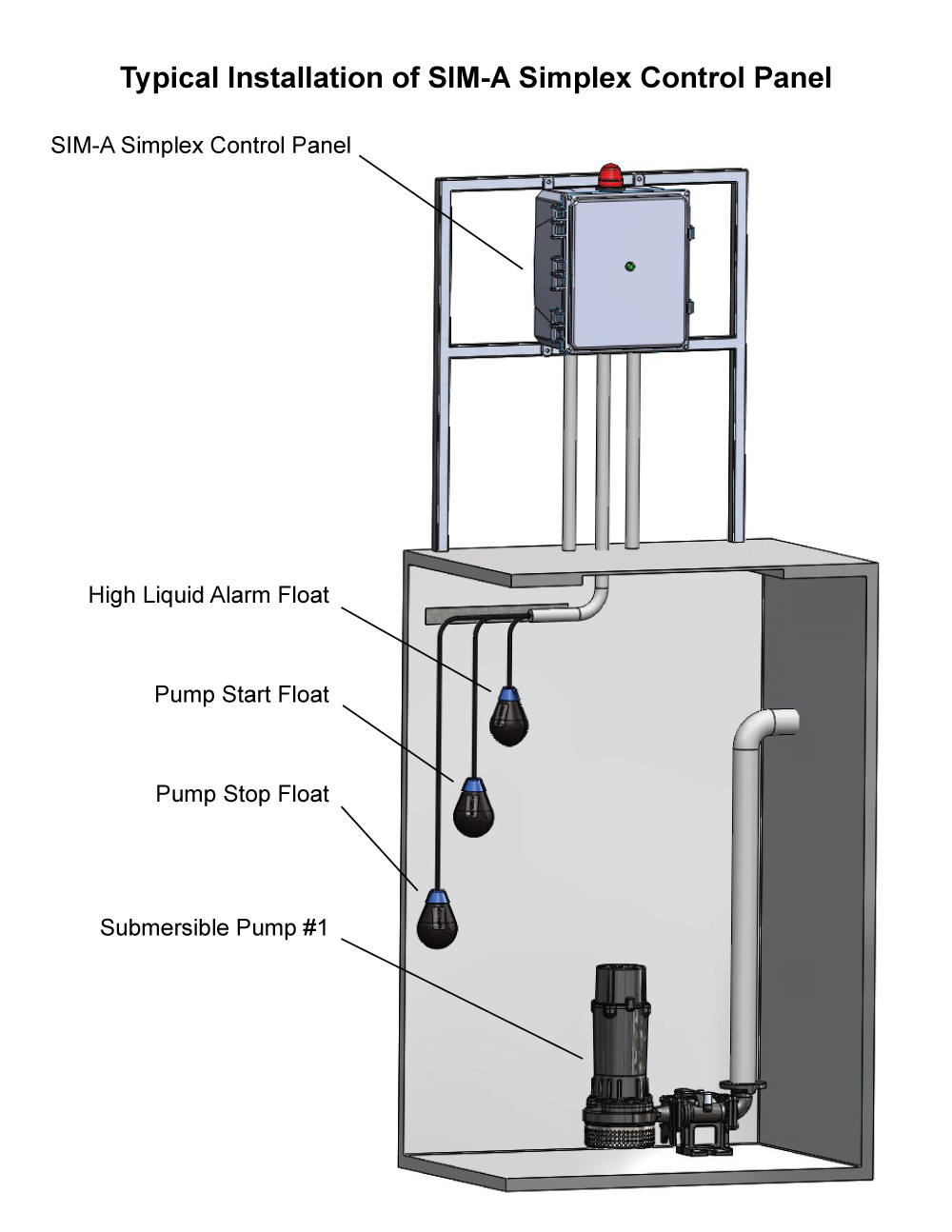
3 phase submersible pump wiring diagram. In the above diagram i shown the magnetic contactor which i also explain the magnetic contactor wired after. 1 111213 page 27 control box wiring diagram cb1456c b1463 l1 460 vac three phase wiring external 3 phase connections 460 vac power source circuit breaker red white black l1 l2 l3 green ground g on indicator lamp m a2 a1 43 2 3 4 1 stop float switch start float. Single phase submersible pump control box wiring diagram 3 wire submersible pump wiring diagram first of all switch of the main circuit breaker in your distribution board this for that reason that you can work. Collection of 3 wire submersible pump wiring diagram. 3 phase submersible pump wiring diagram explanation complete guide the incoming supply goes to mccb circuit breaker. A wiring diagram is a streamlined traditional photographic representation of an electrical circuit.
If the conduit runs into a control box before continuing to the water pressure switch chances are you have a three wire pump. The above diagram is a symbol diagram here is another diagram from which you can also learn easily so for better understand or if did not understand then watch the below. Above in the figure above i showed the magnetic contactor which i also explain the magnetic. It reveals the elements of the circuit as streamlined forms and also the power and signal links in between the gadgets. A submersible pump can be either two or three wire regardless of the voltage coming from the panel so start at your pump and follow the conduit back. Jun 19 2017 single phase 3 wire submersible pump control box wiring diagram or single phase submersible pump starter wiring diagram and wiring installation guide.
St4st6 series submersible pumps operation and parts manual rev. I shown the three poles mccb breaker which is for controlling the. I showed the three poles mccb breaker which is to control the. If it runs straight to the pressure switch it is a two wire. Then connect the supply to input wire connectors. It shows the elements of the circuit as simplified forms and also the power as well as signal links between the devices.
A wiring diagram is a simplified standard pictorial depiction of an electrical circuit. Single phase submersible pump motor control box wiring explanation video tutorial. Here is the complete diagram of single phase submersible pump starter wiring diagram below. Single phase wiring diagrams single phase wiring diagram for 05hp pumps with governor switch single phase wiring diagram with governor switch single phase wiring diagram without governor switch three phase wiring diagrams three phase 208v wiring diagram three phase 230v wiring diagram three phase 460v wiring diagram three phase 575v wiring diagram kb pump wiring diagrams kb pump 230v wiring.


