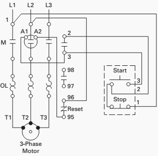
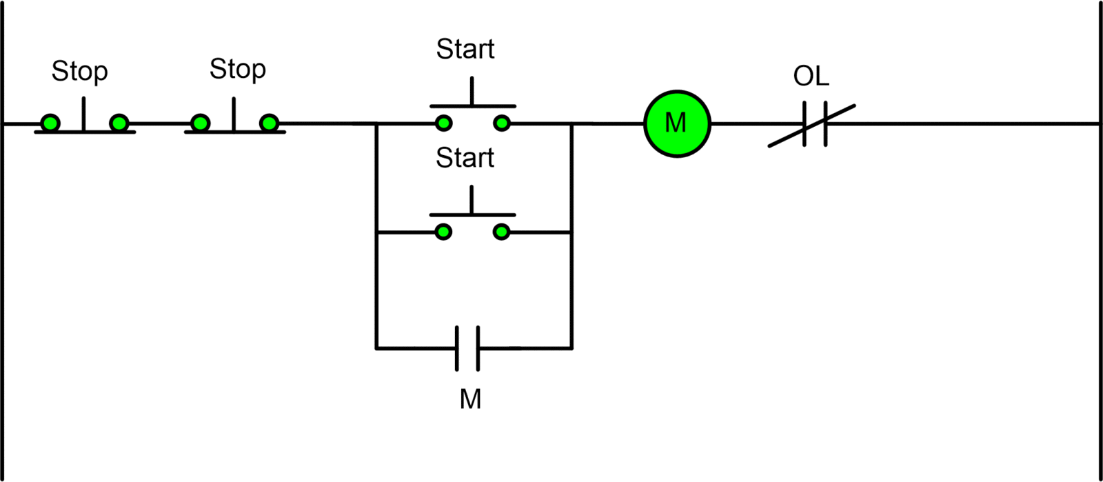
Starting a three phase motor. I operation depressing the start button energizes coil m hold in contacts m and maintains the circuit after the start button is released.

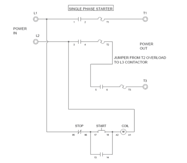
Single Phase Starter Wiring Diagram Wire 9 Trickanddance De
3 phase contactor wiring diagram start stop pdf. Wiring diagram book a1 15 b1 b2 16 18 b3 a2 b1 b3 15 supply voltage 16 18 l m h 2 levels b2 l1 f u 1 460 v f u 2 l2 l3 gnd h1 h3 h2 h4 f u 3 x1a f u 4 f u 5 x2a r power on optional x1 x2115 v 230 v h1 h3 h2 h4 optional connection electrostatically shielded transformer f u 6 off on m l1 l2 1 2 stop ol m start 3 start start fiber optic. How to wire a contactor and. 1 j start 2 3 stop i no. Start stop 3 phase motor starter wiring thomas shues world. With this kind of an illustrative guidebook you will be capable of troubleshoot prevent and complete your projects without difficulty. Ensure that all wiring is fully tight.
Then you connect the 2 motor leads to t1 and t3. Start stop 3 wire control. Start stop 3 wire control. Contactor wiring diagram you will want a comprehensive professional and easy to know wiring diagram. Depressing the stop button breaks the circuit de energizing. Start stop control wiring diagrams single station basic circuit r 1 klai.
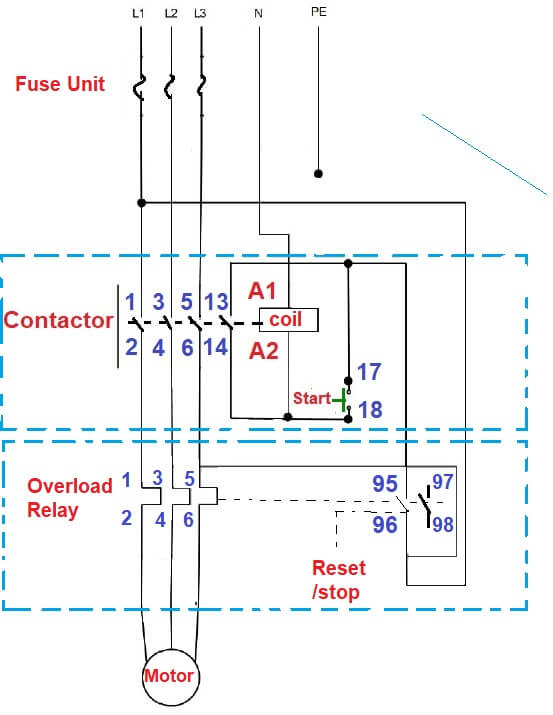
How to do contactor wiring for 3 phase induction motor with 3 pole circuit breaker overload relay nonc push button switches in this tutorial post i will tell you about motor contactor wiring and its diagram. Motor starter schematic and wiring diagram. Wiring should be done when power is off. I zl ii i i ii i i fo 0. The below wiring diagram shows how we would assemble a complete motor starter with a startstop button for a single phase motor utilizing a 3 pole contactor. Tutorial 1 basic push start stop contactor.
The most common use of 3 wire control is a startstop control. Using this method the current is balanced between the 3 poles on the overload. When you press the start button and the stop button is not pressed the 24vdc relay energizes and it pulls in the r1 contactor that feeds three phase power to the motor. Identify the manufacturers info on the two input pins and the output contact use a cable stripper to avoid jutting wires during connections after identifying the input and output terminals start the connections. Ladder diagram basics 3a nema contactor overview duration. A wiring diagram is a simplified conventional pictorial representation of an.
See image below for an example of 3 wire control being used to pull in a contactor to start a 3 phase motor.

