Compressor source tv 83791 views. How to wire a control switch for a 240 volt pump.

240 Volt 12 Lead 3 Phase Wiring Diagram Wiring Diagrams
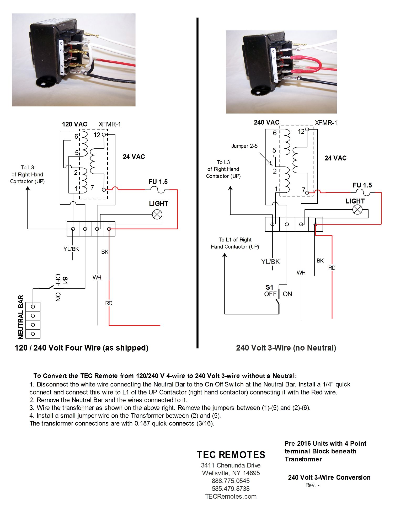
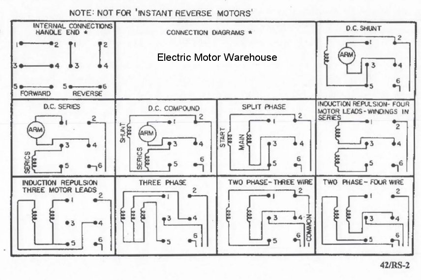
240 volt motor wiring diagram. Open the wiring box cover by removing the screws and verify there are four wires inside the box for wiring the motor. A wiring diagram is a streamlined conventional pictorial depiction of an electric circuit. Learn how a capacitor start induction run motor is capable of producing twice as much torque of a split phase motor. Inst maint wiringqxd 5032008 1002 am page 6. These diagrams are current at the time of publication check the wiring diagram supplied with the motor. To understand how a 240 volt also known as 220 volt household circuit works you should first know a little bit about how a regular 120 110 volt circuit worksif you are at all familiar with residential electrical wiring then you probably already know that in most cases appliances and fixtures connect to three wires.
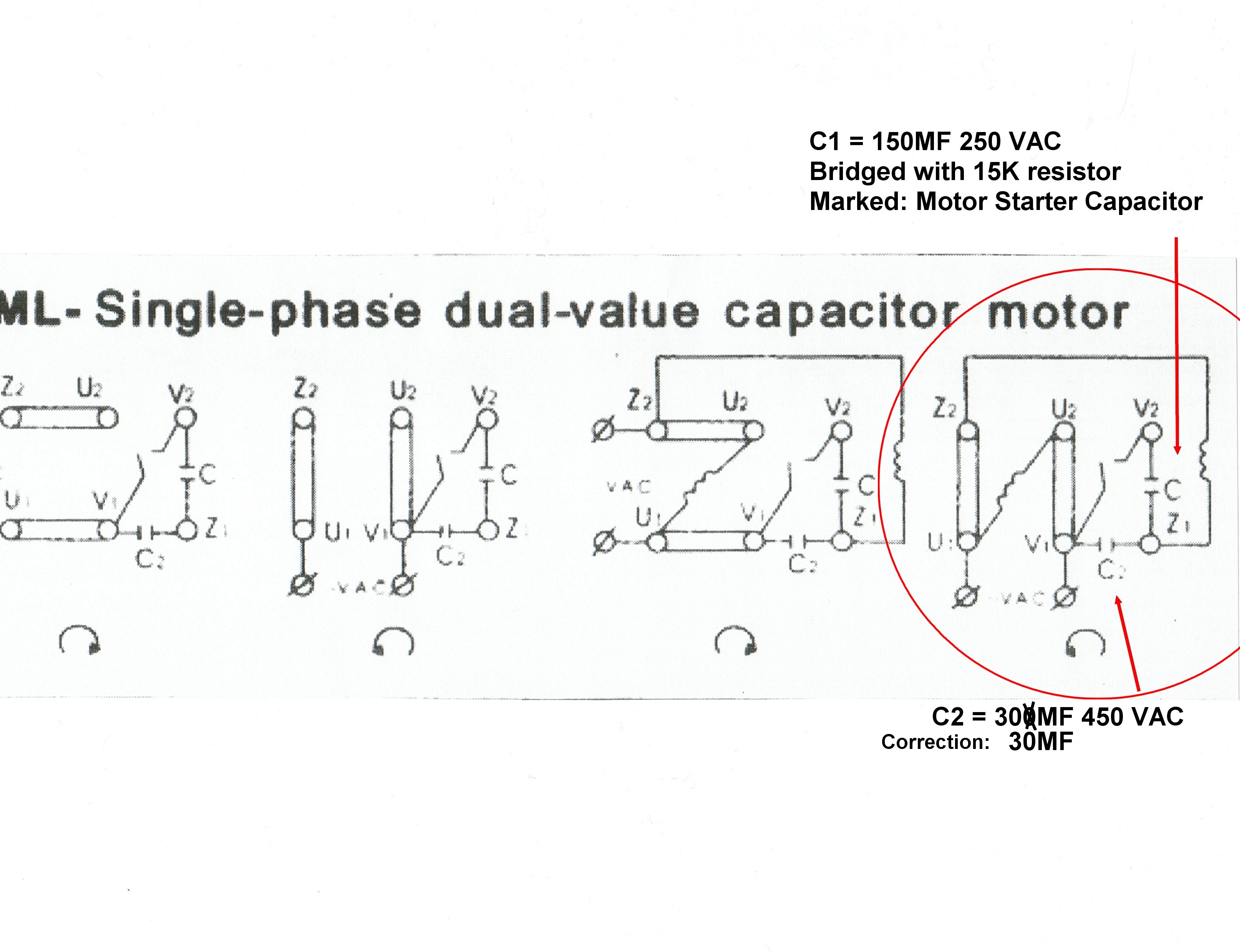
Wondering how a capacitor can be used to start a single phase motor. Wiring a single phase 220 volt. Variety of 240v motor wiring diagram single phase. The wiring diagram will show that two of the motor wires are connected together for 240 volt wiring. The advantages of a 240 volt motor. Also read about the speed torque characteristics of these motors along with its different types.
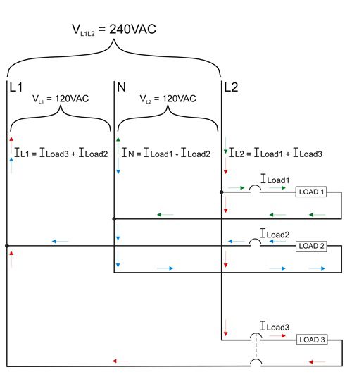
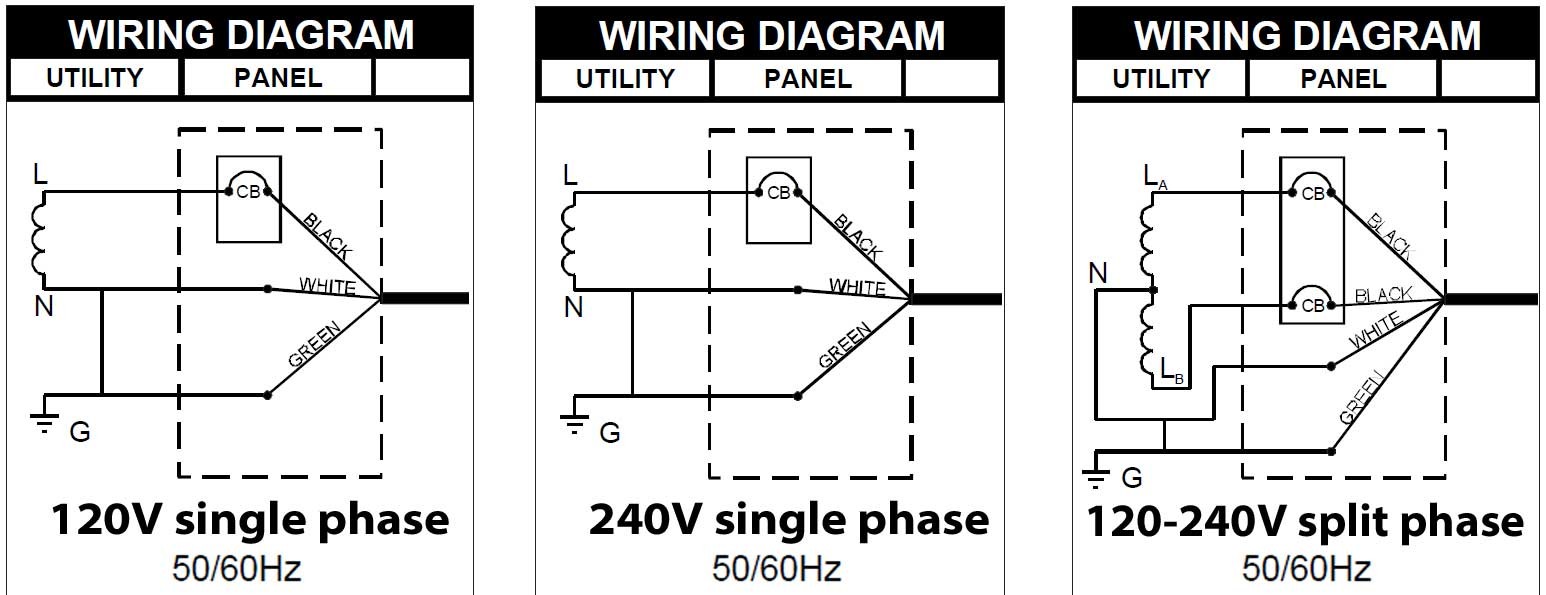
Refer to the motor manufacturers data on the motor for wiring diagrams on standard frame ex e ex d etc. This is because the motors single phase actually operates on the difference between the two 120 volt phases that comprise the residential 240 volt input. Single phase electric motor wiring tutorial. Baldor weg leeson duration. Rewiring a motor from 240 volts to 120 volts duration. Understanding 220 or 240 volt electrical circuits.
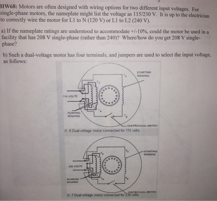
A balanced electrical load which may save on electricity compared to. These tips can be used on most electric motor brands such as weg baldor. With larger motors there may be a larger junction box with lead wires that are identified with numbers or letters which will be identified by the wiring diagram of the specific motor. A double pole switch is the safest way to make sure that both lines of the 240 volt circuit power to the pump are turned off. Wiring a control switch for a 240 volt pump. Wiring a 120240 volt motor for 240 volts is as follows.
When controlling a 240 volt motor it is best to install a double pole switch for this irrigation pump. Single phase 220 volt ac motors are really two phase 240 volt motors especially when compared to three phase 208 volt motors and single phase 120 volt motors. Look at the underside of the cover for the wiring diagram which specifies which wires are used to wire the motor for 240 volts. In this video jamie shows you how to read a wiring diagram and the basics of hooking up an electric air compressor motor. It reveals the components of the circuit as simplified shapes as well as the power and also signal connections in between the tools. Click here to view a capacitor start motor circuit diagram for starting a single phase motor.

