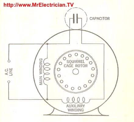
A wiring diagram is a streamlined conventional pictorial depiction of an electric circuit. Single phase electric motor wiring tutorial.
Table Saw Electric Motor Capacitor Wiring Diagram Toyota 7
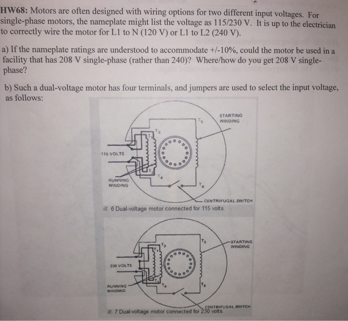
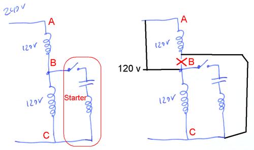
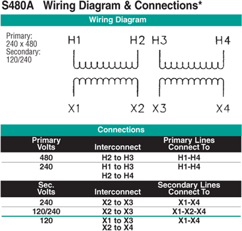
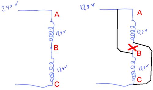
120 240 volt motor wiring diagram. Variety of 240v motor wiring diagram single phase. Reverse ac motor rotation with a square d 2601ag2 drum switch circuit diagram. Reconfiguring between 240 and 120 volts is done the same way but the starter winding stays connected to one of the windings. Single phase 220 volt ac motors are really two phase 240 volt motors especially when compared to three phase 208 volt motors and single phase 120 volt motors. 240 volt motors will have a stronger start compared to a 120 volt motor. The advantages of a 240 volt motor.
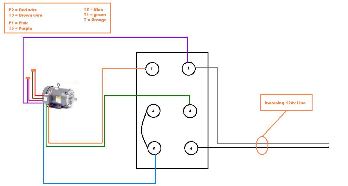
How to change rotation on a dayton 120 volt ac motor. Here is a link to an article that deals with this particular situation. It reveals the components of the circuit as simplified shapes as well as the power and also signal connections in between the tools. Some motors allow both 120 volt and 240 volt wiring by providing a combination of wires for doing so. This is because the motors single phase actually operates on the difference between the two 120 volt phases that comprise the residential 240 volt input. How to convert an outlet or receptacle from 120v to 240v.
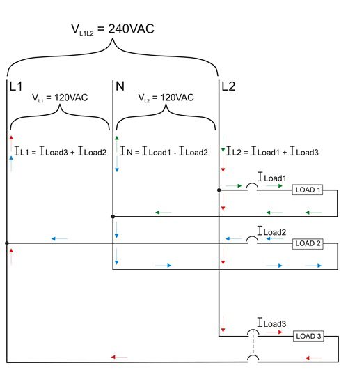
It is actually two 120 volt circuits which share the neutral or common wire. Wiring a motor for 230 volts is the same as wiring for 220 or 240 volts. Wiring a 120 volt circuit off of a 240 volt circuit can be useful where there is primarily 240 volts available. Wiring a 120240 volt motor for 240 volts is as follows. A 240 volt circuit is comprised of two hot wires a common neutral wire and a ground wire. The current draw on the new motor was 16a on 120v.
A balanced electrical load which may save on electricity compared to an unbalanced electrical load. If you dont have a wiring diagram and the motor is currently wired for 240 volts you can identify point b by the fact that it isnt connected to either power lead. This would require supply conductors of 12awg up from the existing 14awg and the breaker from 15a up to a 20a could be allowed to be up to 40a for a dedicated motor circuit. Residential power is usually in the form of 110 to 120 volts or 220 to 240 volts. Be sure you have selected the correct wiring configuration before you begin wiring. This could be the case at a water well or a workshop.

