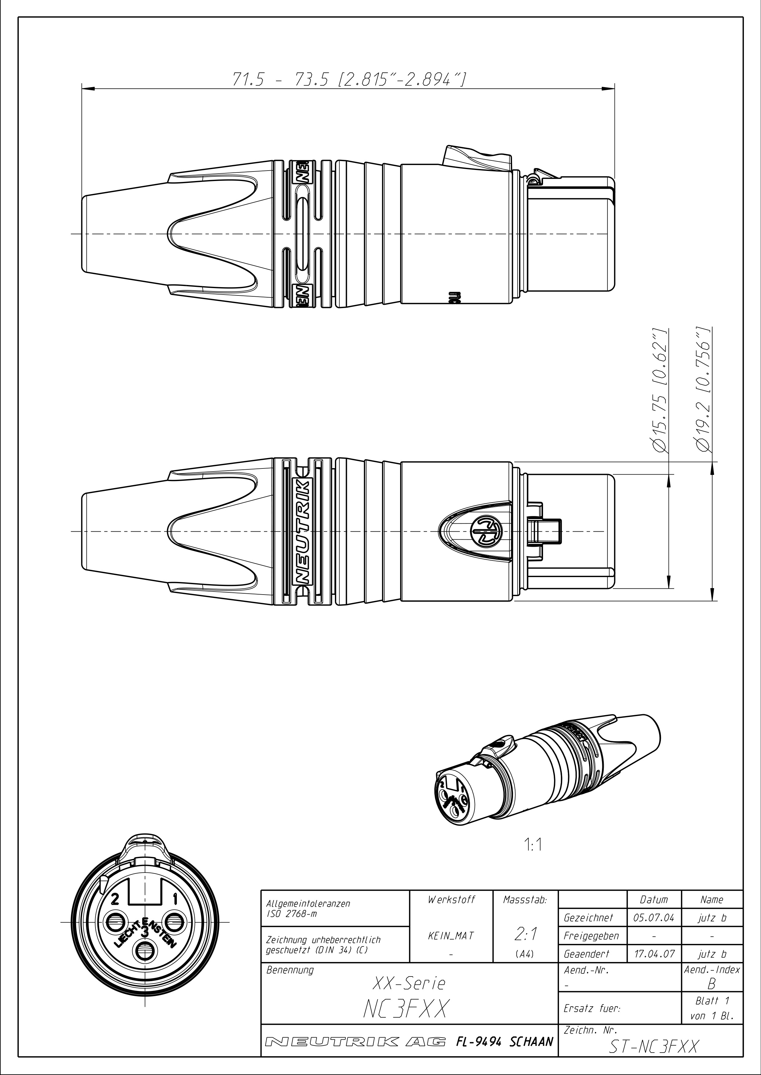
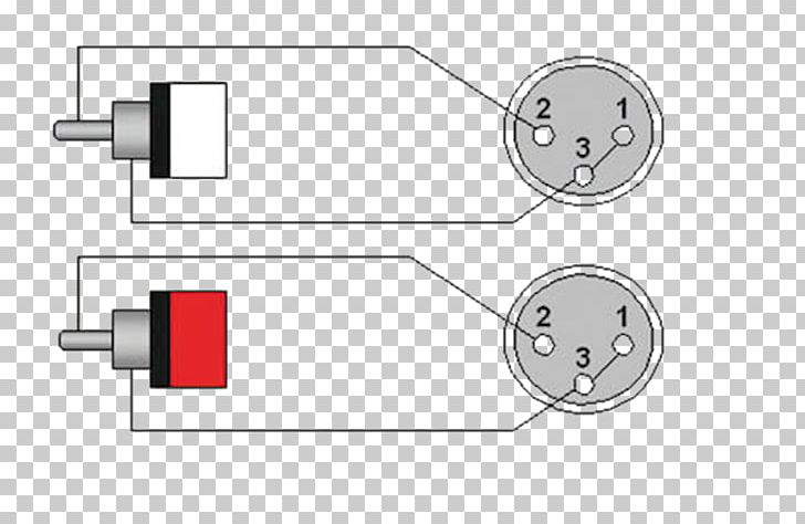
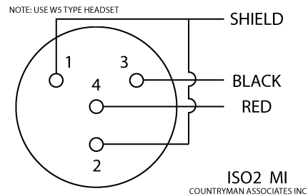
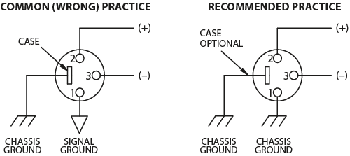
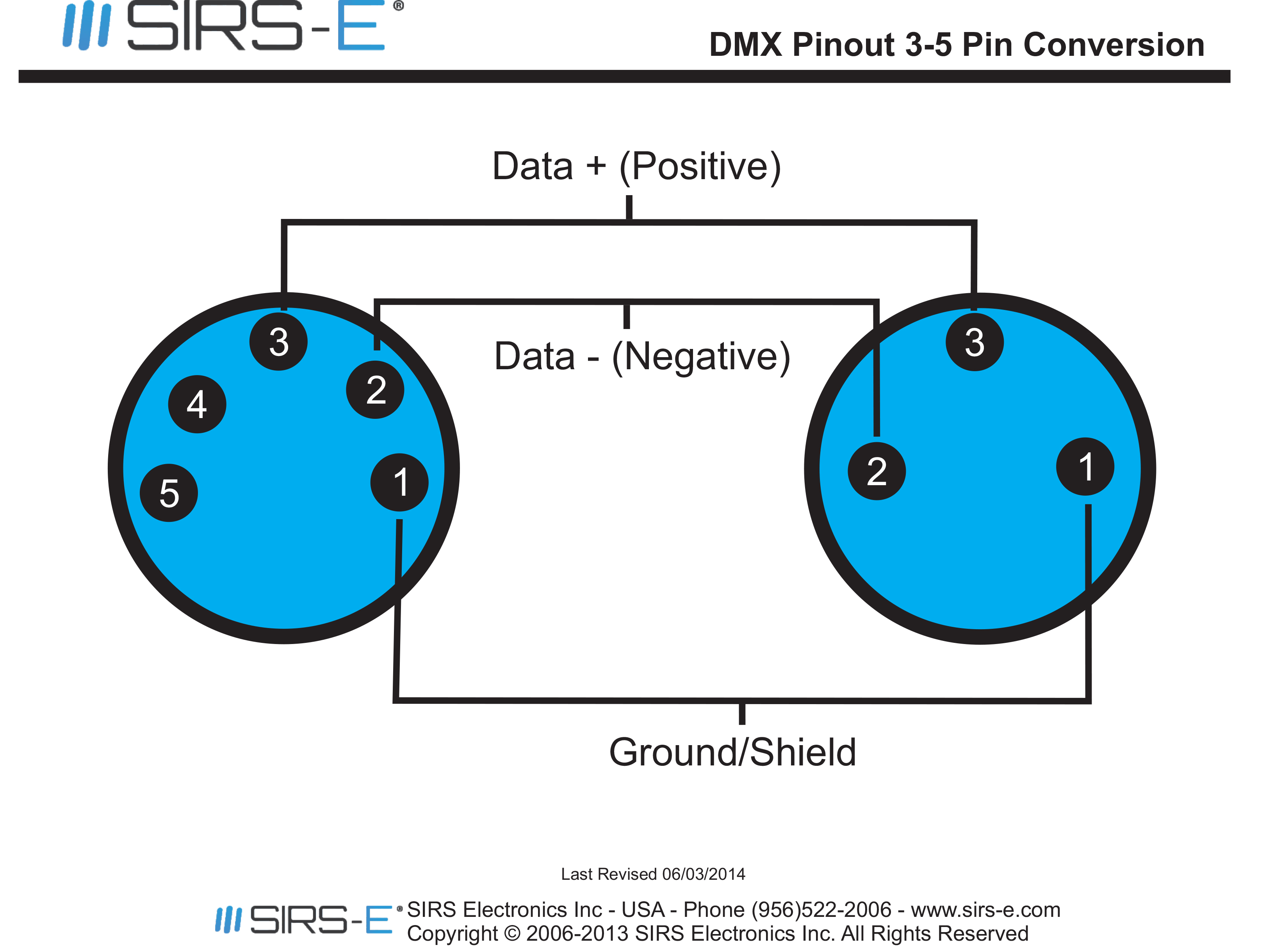
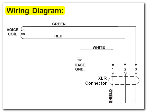
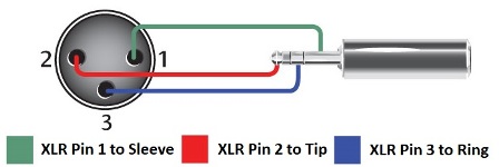
Xlr pin 3 to 14 plug ring. The rear view is the end you solder from here are the connections on each pin.

Switchcraft Aaa Series 5 Pin Xlr Male Cable Mount Connector Gold Pins Black Metal
Xlr cable connection diagram. The xlr connector is pretty straight forward. The following is the aes industry standard for balanced audio xlr wiring commonly known as pin 2 hot. It reveals the components of the circuit as streamlined shapes and the power as well as signal links between the devices. I need to make a cable that goes from xlr to 14. The most comon way to wire a 3 pin xlr to a 14 inch 65mm mono plug sometimes called a jack plug is to join the negative and shield together. If theres a white wire inside your cable your positive end will be red or blue if theres a blue wire with no white wire your positive end will be red.
Some manufacturers especially in vintage equipment do not follow this standard and instead reverse the polarity of pin 2 and 3. Collection of xlr wiring diagram pdf. How should i wire it. The surrounding shield should be soldered to pin 1. The first thing were going to do with our xlr cable is cut both ends of the cable right under the black safeguard removing the male and female ends completely. It shows the elements of the circuit as simplified forms and the power and also signal connections between the tools.
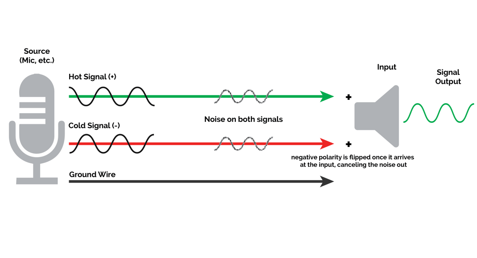
This wiring configuration gives you a balanced mono audio cable. The above diagram shows you the pin numbering for both male and female xlr connectors from the front and the rear view. A wiring diagram is a streamlined conventional photographic depiction of an electric circuit. This can be done by either soldering the shield and negative wires of the xlr to the sleeve of the plug. 3 pin xlr connectors are standard amongst line level and mic level audio applications. Collection of xlr to mono jack wiring diagram.
They are most commonly associated with balanced audio interconnection including aes3 digital audio but are also used for lighting control low voltage power supplies and other applications. A wiring diagram is a simplified standard photographic depiction of an electric circuit. The 14 connector on the other hand can have 2 or 3 wire terminals and is not standard. Xlr pin 1 to 14 plug sleeve. Xlr to 14 mono plug. Xlr pin 2 to 14 plug tip.
It has 3 wire terminals and is standard. The xlr connector is a style of electrical connector primarily found on professional audio video and stage lighting equipmentthe connectors are circular in design and have between three and seven pins. 3 pin xlr wiring standard. Xlr to 14 trs connector wired for balanced mono the usual way to connect a 3 pin xlr to a 14 trs aka stereo jack plug is to use the following pin allocation. There are many different configurations that can be made between an xlr to 14 adapter. 3 pin xlr wiring diagram cable wiring etc cable designed for being cut into standard mic cables may have 2 pairs of wire and a shield around the outside in that case pair the colors together and make sure they go to the same pin number on each end.
3 pin xlr audio pinout.
