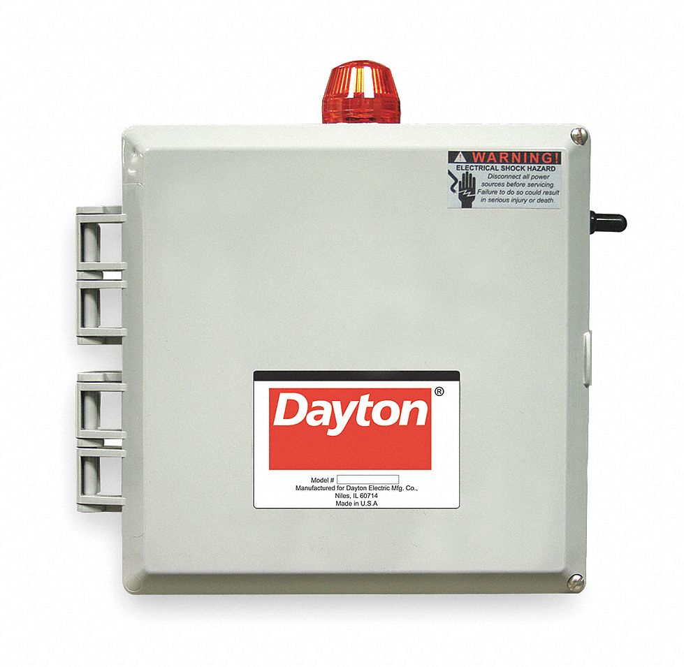
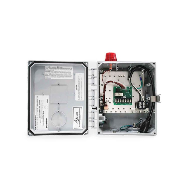
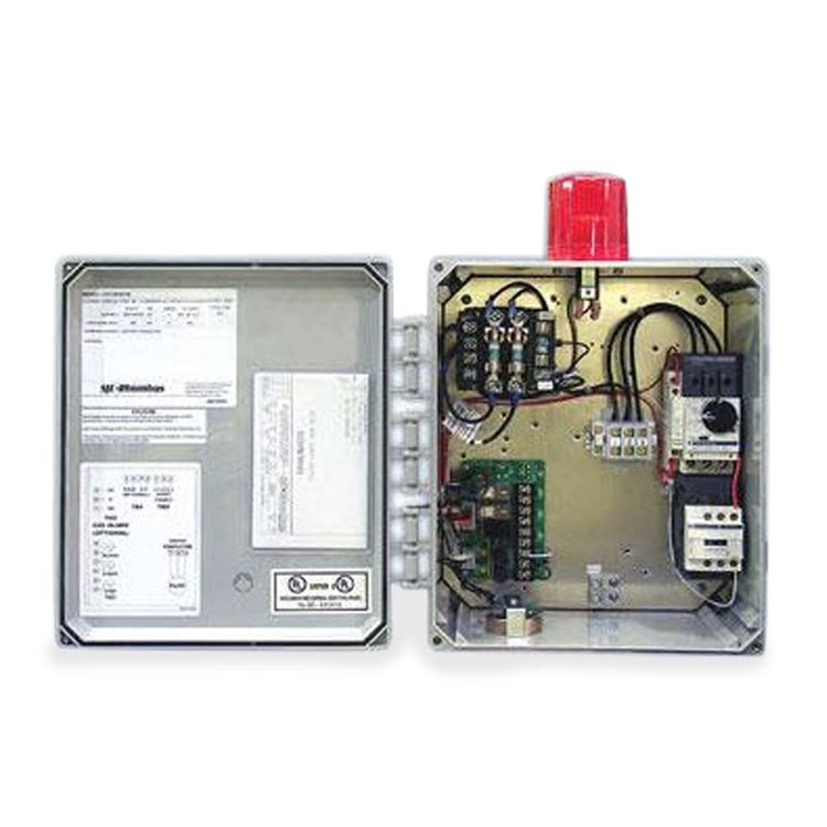
2 wire submersible well pump wiring diagram collections of well pump control box wiring diagram inspirational wiring diagram. The wiring connection of submersible pump control box is very simple.

Gv 6707 Pump Start Box Wiring Diagram And Capacitor Location
Submersible pump panel board wiring diagram. As an example the panel board and circuit to which the gadget connects as well as to determine which of several kinds of fixture are to be set up at that location. We are using reputed brand switchgear and motor protection device like. Use this guide to find which circuit is your submersible pump and turn it off. Start at the breaker panel. Now look to see if the breaker takes up two breaker spaces or one. 3 phase submersible pump wiring diagram.
Collection of 3 wire submersible pump wiring diagram. Not only a contactor but also i install the thermal overload relay which will protect the motor form burning in case of over current flow to the circuit. Jun 19 2017 single phase 3 wire submersible pump control box wiring diagram or single phase submersible pump starter wiring diagram and wiring installation guide. Dol motor starter control panel was used for operating submersible pump or other electric motors especially for rural agro electrical market and industries. I hope after watching the above single phase submersible pump starter wiring diagram guide video tutorial i hope now you will fully understood the complete submersible pump control starter wiring diagram or installation and now you will be able to wire or make your own submersible pump motor starter however now if you have any question regarding the video tutorial or diagram then you can ask. 3 phase submersible pump control panel circuit diagram 3 phase submersible pump wiring diagram single phase water pump motor wiring diagram how to connect submersible pump wires wiring.
A wiring diagram is a streamlined traditional photographic representation of an electrical circuit. It shows the elements of the circuit as simplified forms and also the power as well as signal links between the devices. We can manufactureup 434 kw as per customer specification and design. Here is the complete guide step by step. The main breaker panel should have a wiring schedule handwritten inside the front door panel. In which i control a three phase submersible pump motor using magnetic contactor.
Pump control panel board. Two spaces is a 220 volt system and one is a 110 volt system. In this video i go over the differences of a 2 wire and a 3 wire submersible well pumpthis is associated with the starting components for the pump and whether they are located inside the motor. Circuitry representations will certainly. Single phase submersible pump control box wiring diagram 3 wire submersible pump wiring diagram in submersible pump control box we use a capacitor a resit able thermal overload and dpst switch double pole single throw.
