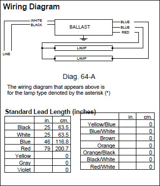
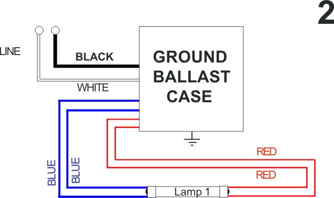
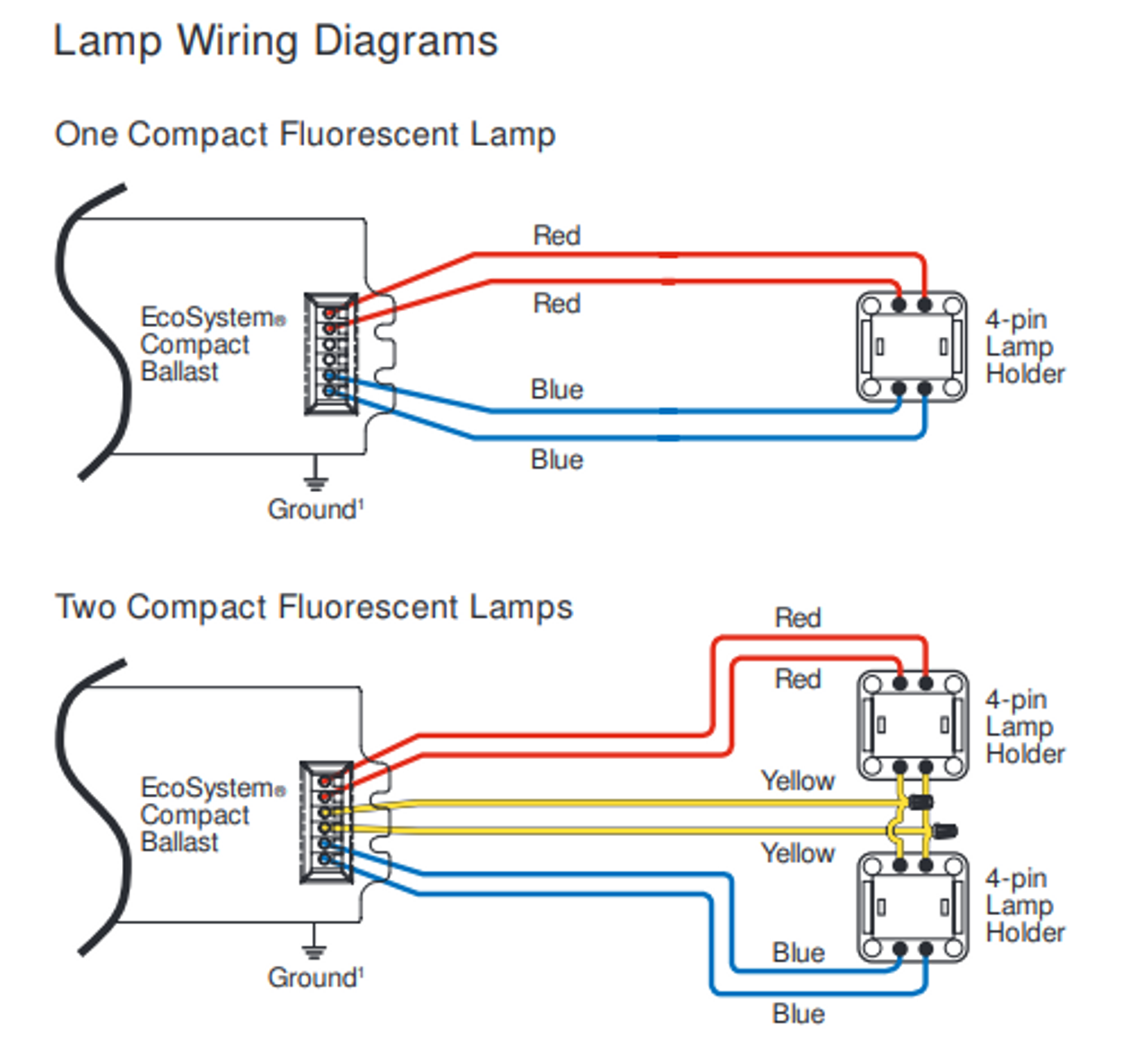
So how to wire the new ballast to my fixture so it works. Some are rated for only 120 volts.
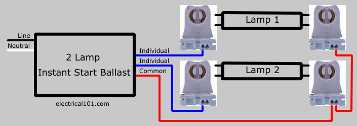
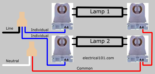
Direct Wire Dual Ended Led Tube Lights 2 Lamps Electrical 101
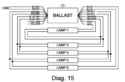
Wiring diagram for fluorescent ballast. A wiring diagram is a streamlined standard pictorial representation of an electric circuit. Variety of fluorescent ballast wiring schematic. Follow the colore coded wiring diagram was the recommendation yet after connecting all like colors on the new ballast to the fixture all i got was a delayed dim light at the base of each fluorescent bulb. It reveals the elements of the circuit as streamlined shapes and the power and also signal links in between the devices. Ballast manufacturers like phillips offer technical support including a telephone number to call for assistance. What can be intimidating is the plethora of wiring diagrams on the new ballast none of which matches exactly the wiring diagram on the original unit.
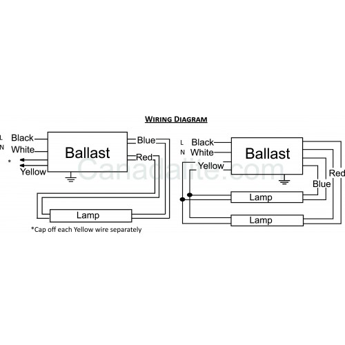
Series ballasts can only be wired in series according to the diagram on the ballast. Newer fluorescent ballasts are usually rated for both 120 volts and 277 volts. Ballast wiring diagram shows how the ballast is wired to the lamps ballast wiring diagram. I suspect the wiring is not as simple as described. It reveals the components of the circuit as streamlined forms and the power and also signal links in between the gadgets. Changing the wiring on a fluorescent light fixture from series to parallel involves changing the ballast from a series to a compatible parallel ballast.
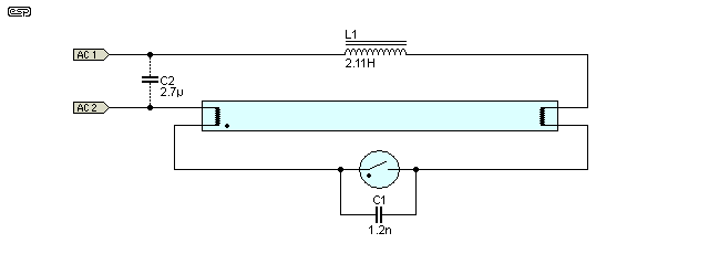
Assortment of fluorescent ballast wiring diagram. Fluorescent lamps use a ballast which transforms line voltage to a voltage to start up and operate the lamps. A wiring diagram is a streamlined standard pictorial representation of an electrical circuit. Parallel ballasts can only be wired in parallel according to the diagram on the ballast. In concept replacing a fluorescent lamp ballast or transformer is pretty simple.

