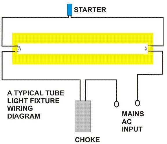
Fluorescent lamps use a ballast which transforms line voltage to a voltage to start up and operate the lamps. Newer fluorescent ballasts are usually rated for both 120 volts and 277 volts.

Bmw X3 Ballast Wiring Diagrams Toyota Aero Zografisch Nl
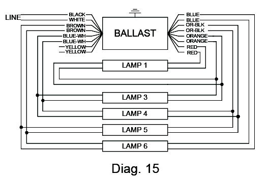
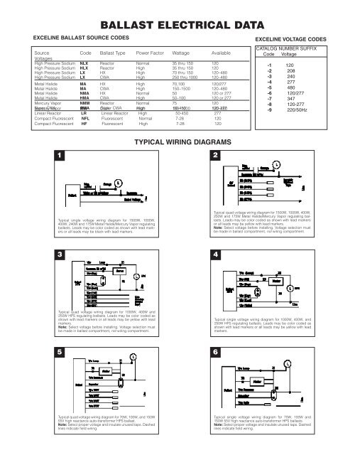
How to read a ballast wiring diagram. Take care to read the wiring diagram on the original ballast and on the replacement ballast to make proper electrical connections. 1 lamp rapid start ballast diagram. Changing the wiring on a fluorescent light fixture from series to parallel involves changing the ballast from a series to a compatible parallel ballast. Parallel ballasts can only be wired in parallel according to the diagram on the ballast. Remove the ballast from the. A wiring diagram is a simplified standard photographic depiction of an electrical circuit.
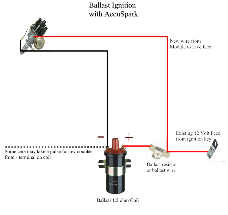
So i bought 2 ge proline t12 ballast for 2 f96t12 this one had a black and white wire when in doubt read the wiring diagram on the ballastwiring diagrams ge survivor t12ho fluorescent all weather sign ballasts figure 4 figure 5 figure 6 figure 7 figure 8 figure 9. Its purpose is to show you step by step how to convert your current 4 foot t8 or t12 fluorescent tube light fixture to use the starled ballast. Dear visitors when you are searching the new ballast resistor wiring diagram electrical wiring representation collection to read this day ballast resistor wiring diagram can be your referred wiring diagram. Variety of 2 lamp t12 ballast wiring diagram. Yeah also numerous wiring representations are offered this electrical wiring layout can take the reader heart a lot. Ballast wiring diagram shows how the ballast is wired to the lamps ballast wiring diagram.
Wiring diagram how to bypass ballast for led tube. Some replacement ballasts are designed to handle multiple situations so you may find that you do not need to use all of the wires on the new ballast. Cut back additional wiring on opposite side of ballast as the led tube lamp only requires power at one end. Some are rated for only 120 volts. It reveals the components of the circuit as streamlined shapes and also the power and also signal connections between the devices.


