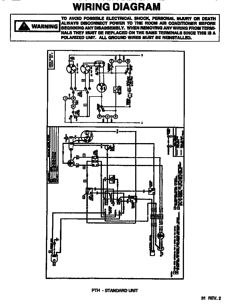
A wiring diagram is a simplified conventional pictorial representation of an electrical circuit. It reveals the parts of the circuit as simplified shapes as well as the power and also signal links between the tools.

Goodman Air Handler Wiring Diagrams Wiring Diagrams
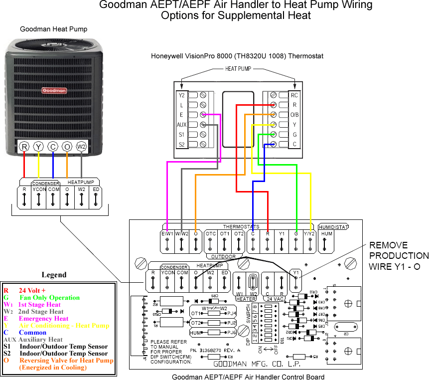
Wiring diagram for a goodman heat pump. As shown in the diagram you will need to power up the thermostat and the 24v ac power is connected to the r and c terminals. C is known as the common terminal. Heat pump thermostat wiring a typical wire color and terminal diagram. These two connections will ensure that there is power to the thermostat that you are operating. Variety of goodman heat pump air handler wiring diagram. Goodman heat pump package unit wiring diagram exactly whats wiring diagram.
Circuitry layouts are made up of two points. It shows the components of the circuit as simplified forms and also the power and also signal connections between the gadgets. The color of wire r is usually red and c is black. Variety of goodman heat pump wiring schematic. A wiring diagram is a simplified standard photographic depiction of an electrical circuit. Goodman heat pump wiring diagram download heat pump wiring diagrams goodman wire colors thermostat diagram.
A wiring diagram is a kind of schematic which utilizes abstract photographic icons to show all the interconnections of elements in a system. Low voltage is the voltage that is used to control the unit from a thermostat or other controlling device. High voltage is the voltage the unit needs to run. Heat pump wiring diagram unique goodman air handler wiring diagram. Goodman air handler wiring diagram elegant heat pump stunning. Goodman heat pump wiring diagram awesome goodman heat pump wiring.
In the goodman heat pump there are two wiring sources that have to be connected. Symbols that stand for the parts in the circuit and lines that represent the. These two sources are high voltage and low voltage.


