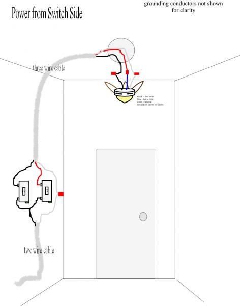
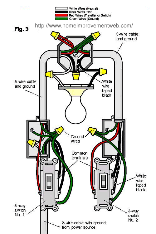
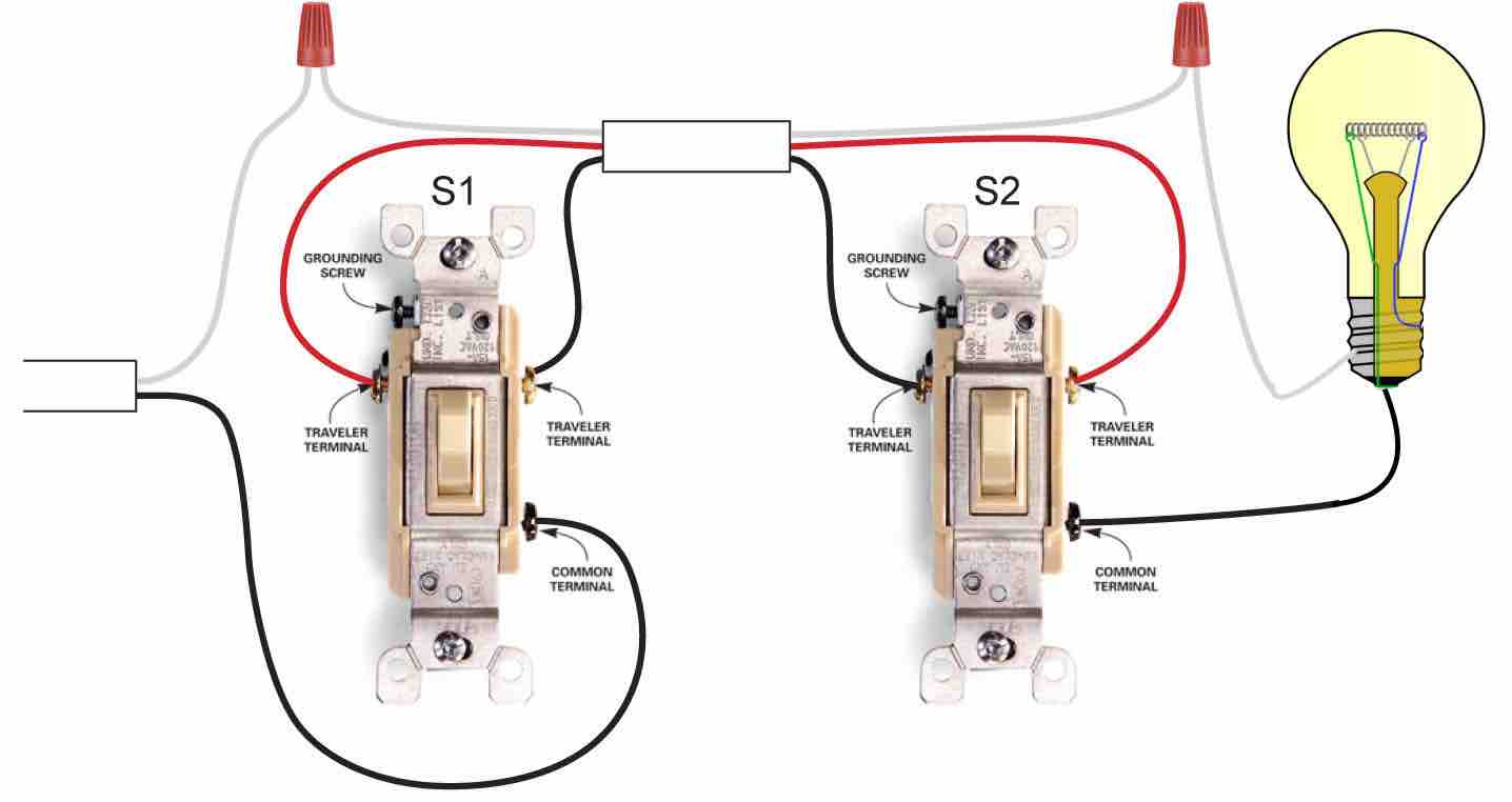
The common on the second 3 way switch is connected to the hot wires on the fanlight. So what you should see if you have correct 3 wire electrical cable romex is a black power white neutral and now a 3rd red wire.
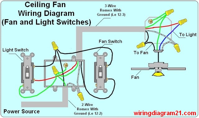
Ceiling Fan Wiring Diagram Light Switch House Electrical
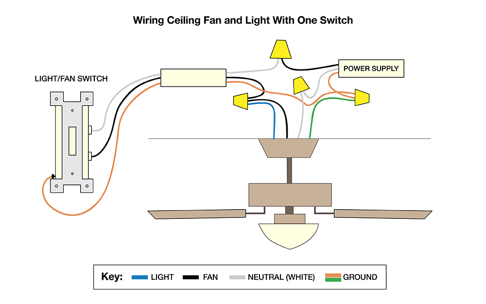
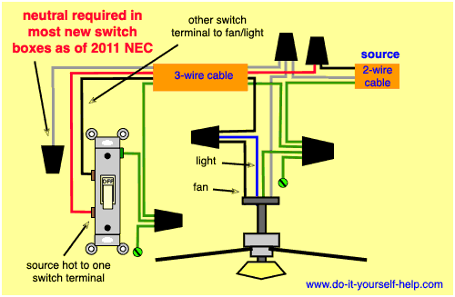
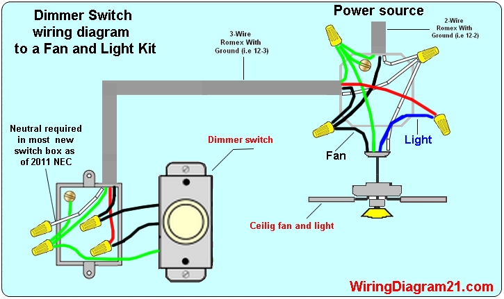
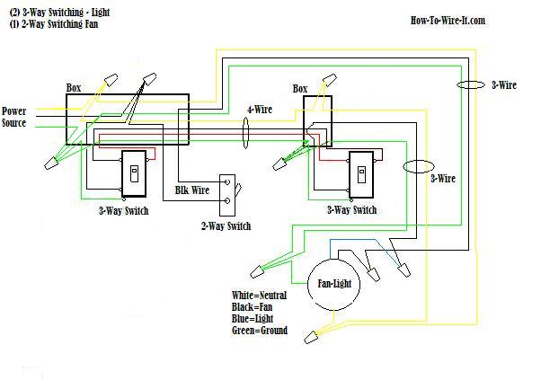
Wiring diagram 3 way switch ceiling fan and light. In this diagram the black wire of the ceiling fan is for the fan and the blue wire is for the light kit. Here a ceiling fan with a light kit is controlled with two 3 way switches. Assortment of wiring diagram 3 way switch ceiling fan and light. A wiring diagram is a straightforward visual representation of the physical connections and physical layout of the electrical system or circuit. Ceiling fan 3 way switch wiring. Regardless of what 3 way switch wiring diagram youre following youll need to use a 3 wire cable to connect the two 3 way light switches.
It shows the elements of the circuit as streamlined forms and also the power and also signal connections in between the devices. Ceiling fan 3 way switch wiring diagram ceiling fan 3 way switch wiring diagram hunter ceiling fan 3 way switch wiring diagram every electric arrangement consists of various diverse components. Ground connection diagram is shown separately. Each component should be set and connected with other parts in specific manner. Wiring diagram 3 way switch ceiling fan and light what is a wiring diagram. In this wiring the source is at sw1 and 3 wire cable runs between each switch and the ceiling fan.
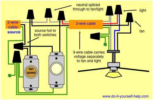
To wire a 3 way switch circuit that controls both the fan and the light use this diagram. This is the same arrangement as the second diagram on this page with a fan in place of the light fixture. In the ceiling light fixture electrical box one black wire from a 3 way switch gets connected to the black load wire on the light fixture. The light kit will switch to the red wire of the 3 way cable and the fan control switch will connect to the black wire. A wiring diagram is a streamlined conventional photographic depiction of an electrical circuit. The fan control switch usually connects to the black wire and the light kit switch to the red wire of the 3 way cable.
3 way switch wiring diagram depicting all wires in the ceiling junction box. If not the structure will not function as it should be. In the above 3 way switch wiring diagram at each switch the black wire gets connected to the copper or black screw. 3 way fan switch wiring diagram. The line voltage enters the switch outlet box and the hot wire will connect to every switch. Switch hots and line neutral will connect to a 3 wire cable that travels to the fanlight outlet box in the ceiling.
As with all 3 way circuits the common on one switch is connected to the hot source wire from the circuit.
