About the type of construction methods used. Designing home wiring layouts.
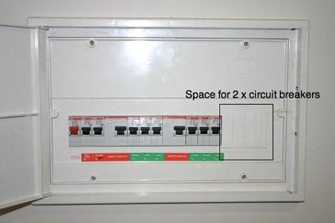
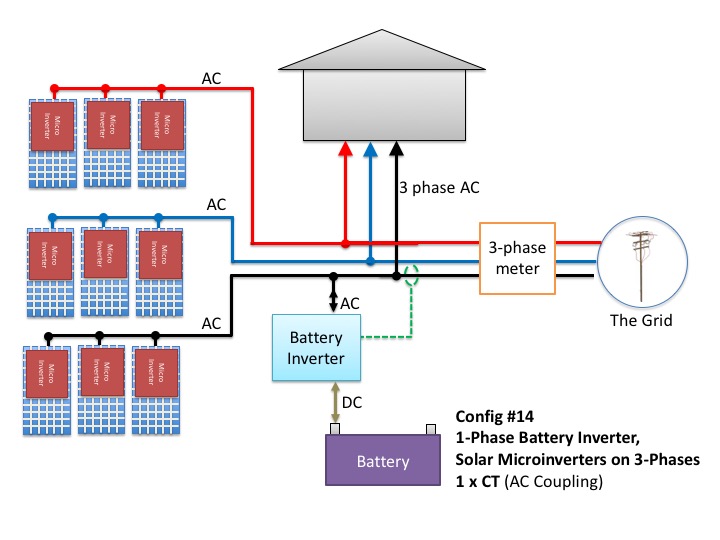
Switchboards And Meters Are They Solar Power System Ready
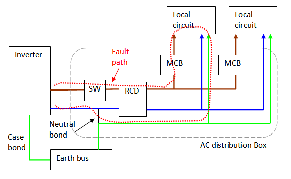
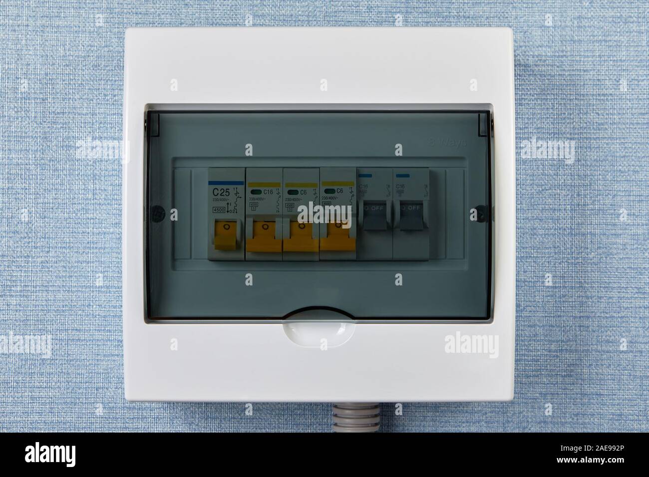
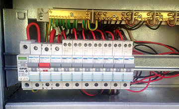
Domestic switchboard wiring diagram. The detailed internal wiring for the sample db and mcbs and rcd units used domestic switchboard wiring diagram nz. Before selecting a wiring system for an installation you need to know something. Wiring of the distribution board with rcd single phase from energy meter to the main distribution board fuse board connection electrical technology domestic switchboard wiring diagram nz. The switchboard protects the electrical wiring system in your home. The following explanation will help you understand better how to design home wiring layouts. It shows how the electrical wires are interconnected and can also show where fixtures and components may be connected to the system.
Wiring diagram of single phase distribution board with rcd in nec us iec uk eu electrical wiring color codes. Learning notes final sub circuits. A final sub circuit is a circuit from a switchboard to which only consuming devices or points are connected. Domestic switchboard wiring diagram mmucc thousands collection of electric wiring diagram mazda 3 fuse box horn sunpro tach wiring diagram 1998 honda civic headlight wiring diagram fuse box in jeep grand cherokee nippondenso voltage regulator wiring diagram. These methods will. Below is the given wiring diagram of single phase distribution board with rcd in both nec and iec electrical wiring color codes.
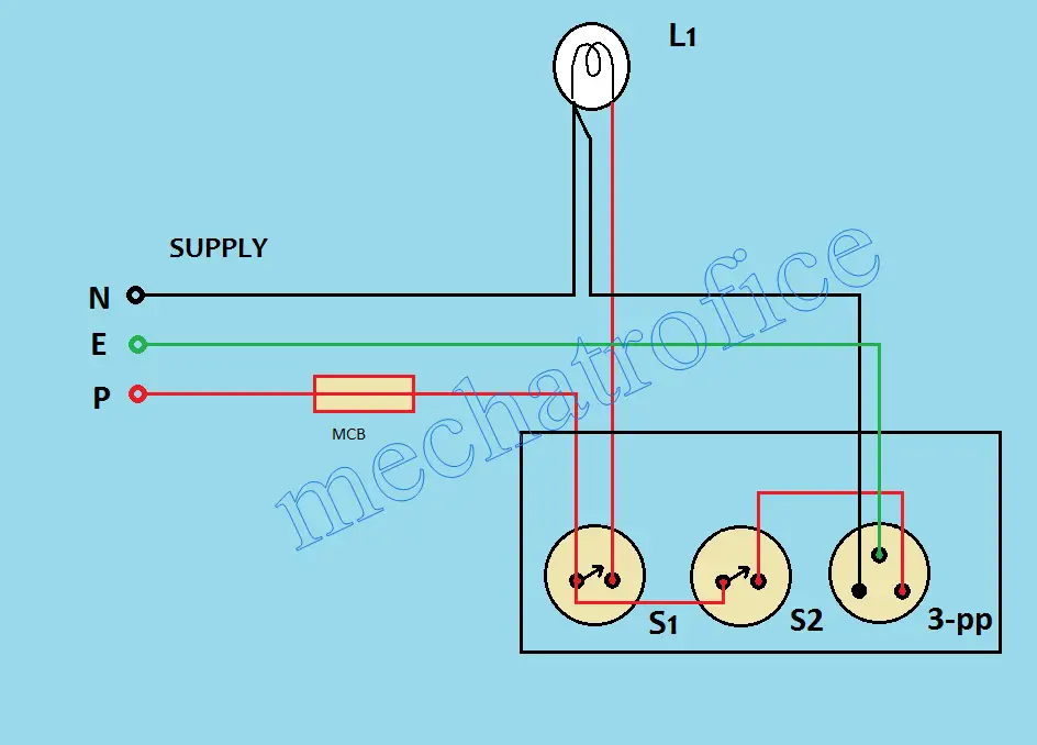
How to wire a switch and a load a light bulb to an electrical supply. The same description and detailes can be used as mentioned for the above fig 1. As can be seen in the diagram the wiring is pretty simplethe phase is invariably applied to one terminal of the switch the other terminal moves to one of the connections of the load and the other. A wiring diagram is a simple visual representation of the physical connections and physical layout of an electrical system or circuit.

