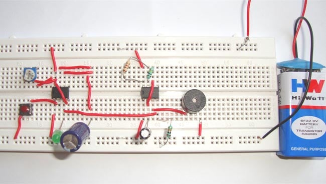
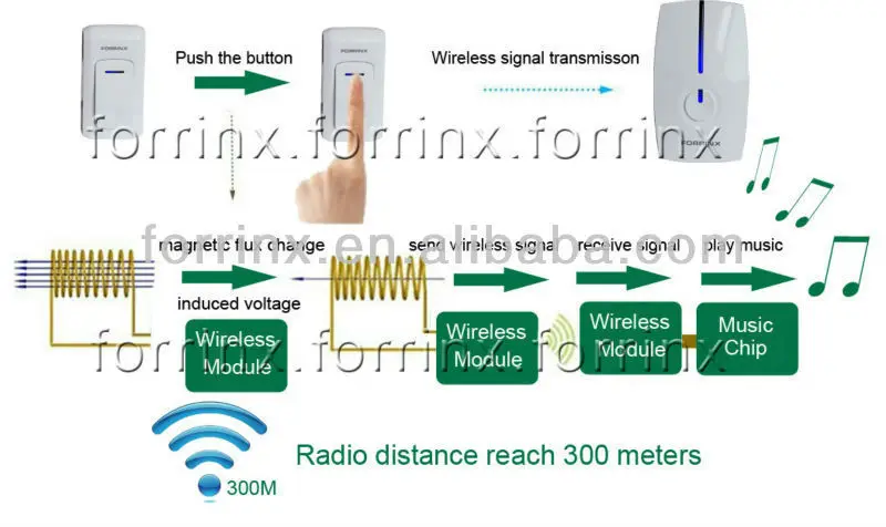
This project is a wireless doorbell so we can get rid of the hustle on the wiring job. So in this tutorial we are going to build a doorbell with 555 timer ic.

Wireless Controlled Door Bell Electronics Project
Wireless doorbell schematic circuit diagram. Wireless doorbell you can learn. Doorbell is a very common and useful device used in every household. The circuit is placed in series with the original doorbell switch and emulates the doorbell switch for the original door bell. Click on your setup to view the diagrams. The wireless doorbell transmitter and receiver circuit are incorporated below. Wiring for two doors is the same as for one with the transformer hardwired to the 120 volt source from a house circuit.
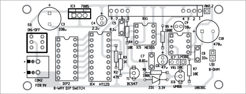
The transmitter circuit is made up of 303mhz rf oscillator and 32khz crystal controlled oscillator. If youre in the process of setting up multiple ring video doorbells internal doorbells and transformers the following wiring diagrams may help. Wireless doorbell this is diagram about circuit project. As the wireless doorbell is wireless based project it is divided into two major section ie. Connect the input wires on the transformer to the source circuit using the black to black white to white and ground to green method. All transistors are 2n3563 the u shape coil is a single half turn using a 1mm copper wire with 5mm diameter the most fundamental constituent is the transistor.
Wiring diagram for a two chime doorbell. 1 provides a mechanical means of striking two gongs or chimes in sequence one when the doorbell is pressed the other when it is released. This project uses rf radio frequency for the transmitter and the receiver circuits to communicate. Among electronics students and hobbyists doorbell circuit project is quite popular. The circuit shown in fig. Horn relay ignition coil ignition switch instrument cluster mazda oldsmobile pontiac power power supply power window radio relay schematic circuit schematic diagram schematic diagrams toyota volvo wiring connection wiring diagram.
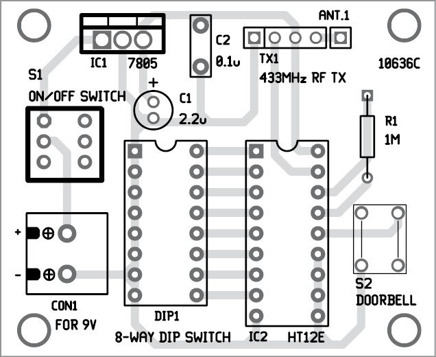
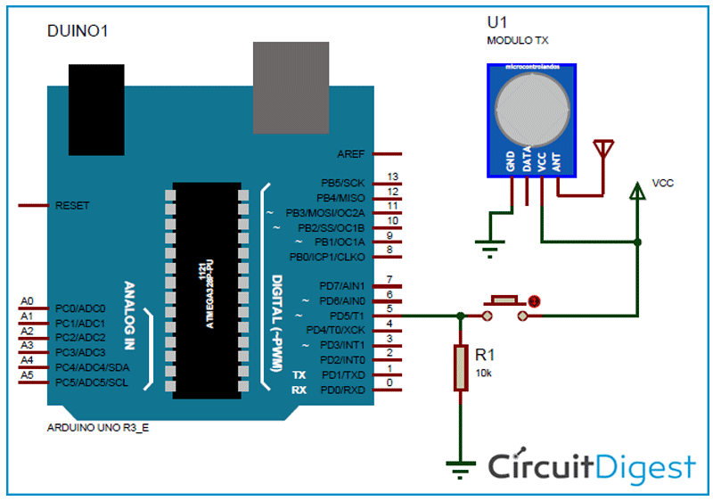
When the doorbell switch is pressed this circuit sends a message via a simple 433 mhz rf transmitter to a wireless doorbell receiver while keeping the original doorbell functionality intact. Wireless doorbell the transmitter circuit is made up of two building blocks the 303mhz rf oscillator and the 32khz crystal controlled oscillator. The circuit of the wireless bell shown here is easy to built and using only few easy to find low cost components. Transmitter this transmitter section is designed around oscillator transistor bf194b t 2 followed by two transistor bc148 t 1 and t 3. The main feature of this doorbell is that we can control the time duration for which it keeps ringing upon pressing the. A um66 melody generator is connected at the output of the receiver circuit which will be activated when the receiver circuit receives signals from the transmitter.


