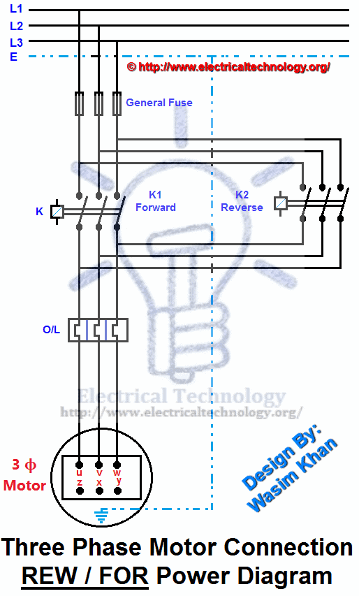
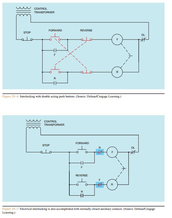
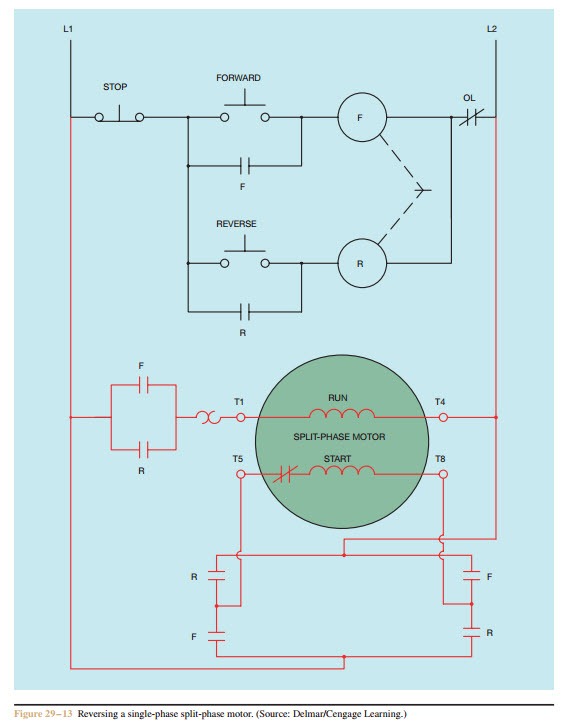
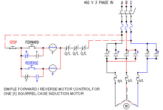
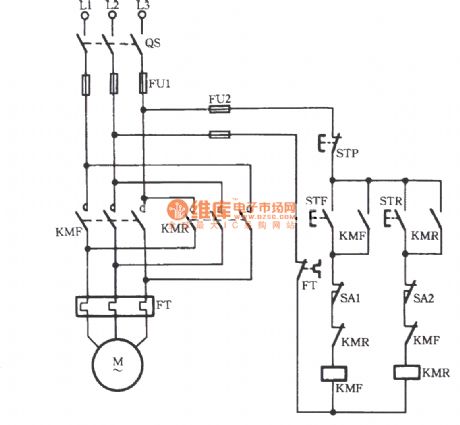
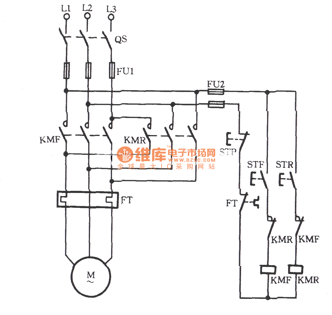
The figure given below shows the control and power diagram of forward and reverse starter diagram. As the name defines forward reverse starter is used to run the motor in both sides forward and reverse.

Interlocking Methods For Reversing Control Basic Control
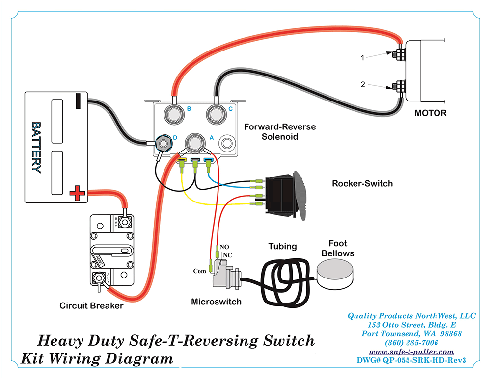
Forward reverse switch circuit diagram. It shows the components of the circuit as streamlined shapes as well as the power and signal connections between the tools. In the diagram i connect the incoming three phase supply l1 l2 l3 to the mccb circuit breaker molded case circuit breaker. Reversing polarity of dc shade motors can be accomplished with a simple dpdt double pole double throw switch. Forward reverse motor control diagram for three phase motor for three phase motor forward reverse control circuit. Motors can be reversed whether powered by battery or power supply. Control circuit for forward and reverse motor checkout video on 4 way switch wiring.
Low voltage protection can be implemented using the overload contact input so that if an overload occurs the motor circuit will turn off. These forward and reverse starters are dol type and not used above the 05 hp motors. This wiring diagram shows how to configure a dpdt switch as an h bridge configuration for reversible blind and shade tubular dc motors. To run the motor of above 05 hp rating circuit has to made. Figure 1 hardwired forwardreverse motor circuit. We use 2 magnetic contactors as forward reverse switch.
A wiring diagram is a simplified standard photographic representation of an electric circuit. However after the overload condition passes the operator must push the forward or reverse push button again to restart the motor. Variety of ezgo forward reverse switch wiring diagram. Here i showed the forward reverse wiring diagram.


