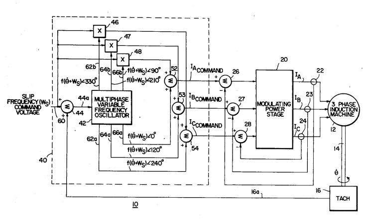
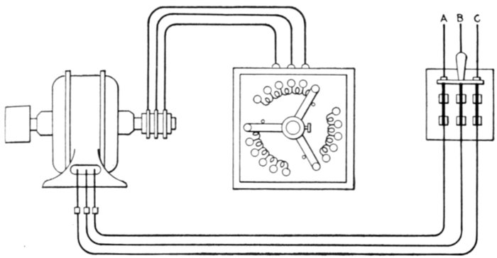
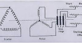
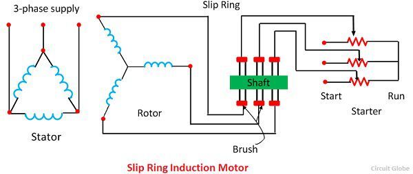
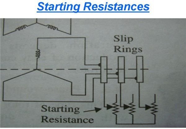
The slip ring induction motor diagram is shown below. An electrical diagram of a slip ring three phase induction motor is shown below.

Magna Start New Generation Slip Ring Motor Starter
Slip ring motor connection diagram. Slip ring induction motor connection diagram why slip rings are used in an induction motor. A complete guide about solar panel installation. The phase difference between the current and voltage is not sufficient to develop high starting torque. Three phase slip ring rotor starter control power diagrams 3 phase slip ring rotor starter control power diagrams slip ring rotor power and control. But how does external resistance aid in better starting characteristics. Spare parts sirus electronet india pvt ltd exploded view of slip ring alternator.
Step by step procedure with calculation. Slip is defined as the difference between the flux speed and the rotor speed. To increase the phase difference the motor is provided with some rings through which high resistance is connected in series with the circuit. Rev for three phase motor connection power and control diagrams. When the motor is running the slip ring are shorted by connecting a metal collar which connects all slip ring together and the brushes are also removed. Also know about the qualities of slip ring induction motors.
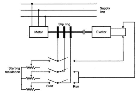
At starting the resistance is connected to the rotor circuit and is gradually cut out as the rotor pick up its speed. Slip rings how does a ring work powerbyproxi wireless. Read here to know about the starting arrangement and the role played by the external resistances in obtaining better starting characteristics. A slip ring induction motor can be started with external resistance added in its rotor circuit. Slip rings how does a ring work powerbyproxi wireless. Component slip ring motor ac buy ringac starter for sale pricechina manufacturer download induction sjr kw st.
For an induction motor to produce torque at least some difference should be there between stator field speed and rotor speed. The working of the motor connection diagram is shown in the figure below.


.png)

