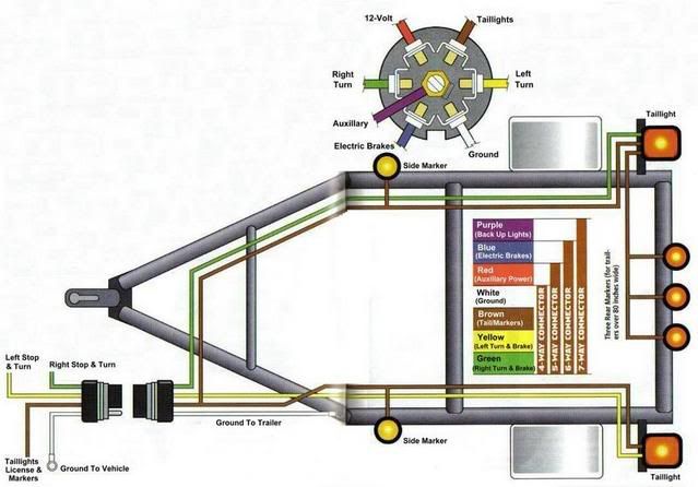
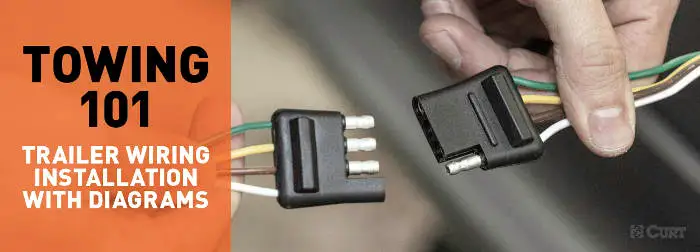
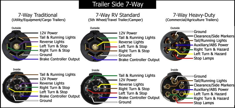
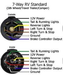
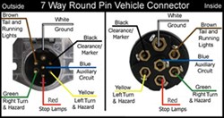
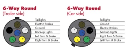
Complete with a color coded trailer wiring diagram for each plug type this guide walks through various trailer wiring installation solution including custom wiring splice in wiring and replacement wiring. If your truck has a built in 7 pin socket but you only need 5 of the pins.

Plug Connector Diagram Trailer Factory Outlets Utility And
Trailer lights connector diagram. The basic purpose remains the same whether your truck and trailer is using a 4 way 5 way 6 way or 7 way connector. Use the 7 pin connector anyway see below and just leave out the last 2 wires. Various connectors are available from four to seven pins that allow for the transfer of power for the lighting as well as auxiliary functions such as an electric trailer brake controller backup lights or a 12v power supply for a winch or interior trailer lights. When wiring trailer lights make sure to route the harness away from anything that could damage the wires. In the trailer wiring diagram and connector application chart below use the first 5 pins and ignore the rest. If a ground problem exists it will show at this point.
Trailer wiring diagrams trailer wiring connectors. The connector on the tow vehicle should have a ground wire secured tightly to a clean unpainted surface on the frame. Trailer electrical connectors come in a variety of shapes and sizes. The places to check grounds are as follows. If your vehicle is not equipped with a working trailer wiring harness there are a number of different solutions to provide the perfect fit for your specific vehicle. When the taillights and brake lights are used at the same time it creates the maximum amp load of the lights on the trailer.
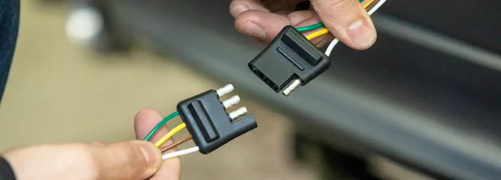
This connector is commonly found on most light duty trailers. On the vehicle side there will be a female connector while the trailerrv harness will have a male connector. By law trailer lighting must be connected into the tow vehicles wiring system to provide trailer running lights turn signals and brake lights.




/trailer-wire-colors-589d62645f9b58819cf8721f.gif)


