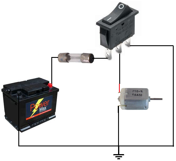
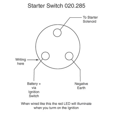
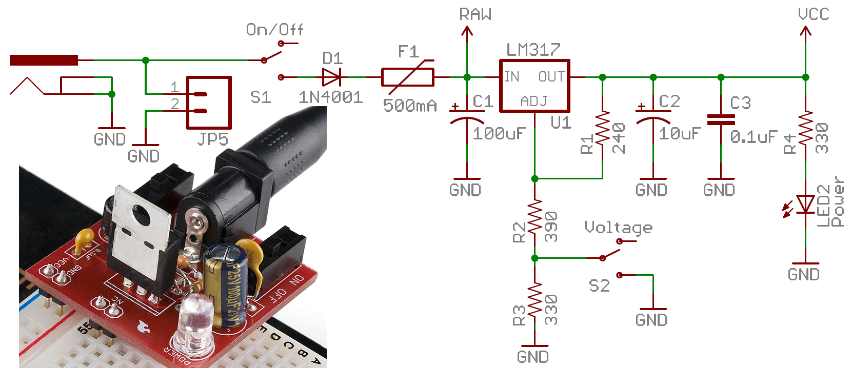
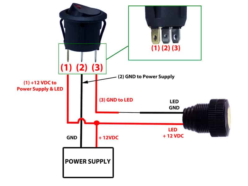
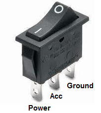
3 pin rocker switch wiring diagram 3 pin rocker switch wiring diagram every electric structure is made up of various distinct pieces. The wiring diagram to the right will show how to wire and power this 12v 20amp on off on 3 way carling contura rocker switch.

Spst Toggle Switch Wiring Diagram H1 Wiring Diagram
3 pin switch wiring diagram. Pin 2 is where the accessory that the switch is going to turn on is connected. Here is a diagram of a spdt toggle switch. A dpdt toggle switch has 6 terminals. Carling toggle switch wiring diagram. Assortment of fender telecaster 3 way switch wiring diagram. Wiring products 814104 views.
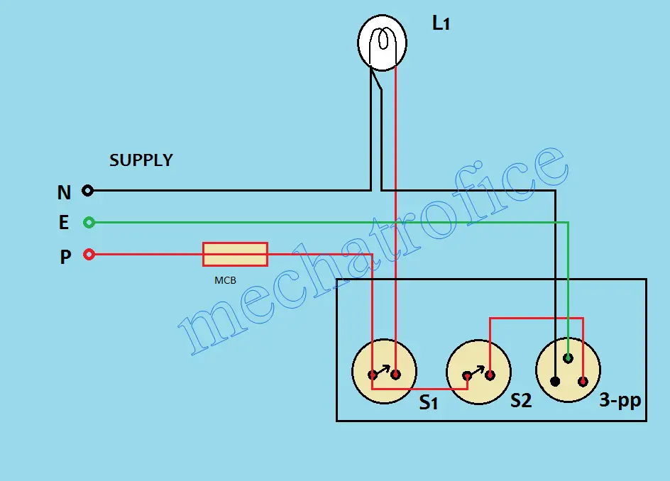
6 pin toggle switch wiring diagram collection 3 prong toggle switch diagram beautiful rocker switch wiring. How to wire an led toggle switch on off 3 prong rocker switch 2020 duration. 9 pin toggle switch wiring diagram 6 pin rocker switch wiring. This wiring diagram is impotent because by using this wiring connection a person can easily switch off the 3 pin socket or can easily switch on by using the circuit breaker. Illuminated on off rocker switch with wiring products duration. As long as power is connected to the switch one is always on.
Each part should be placed and connected with different parts in particular manner. Switched 3 pin socket or how to control a 3 pin socket from a circuit breaker. A wiring diagram is a simplified conventional photographic depiction of an electric circuit. We will now go over the wiring diagram of a dpdt toggle switch. It reveals the elements of the circuit as streamlined forms and the power and also signal links between the devices. It shows the elements of the circuit as streamlined shapes and the power and also signal links in between the devices.
A wiring diagram is a simplified conventional photographic depiction of an electric circuit. Below is the schematic diagram of the wiring for connecting a dpdt toggle switch. Terminals 3 and 4 represent the toggle switch. Pin 1 is where the rocker switch receives the input power. Or these terminals can be ignored for non backlit switch banks. Terminal 2 is connected to power.
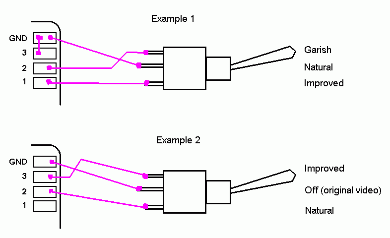
This translates into the following model in a real life rocker switch. 3 position toggle switch wiring diagram elegant switches can a. Terminal 1 is connected to one load or accessory terminal 3 is connected to another load or accessory. Below is a pictorial representation of the schematic diagram. When wiring this switch you can choose if youd like to illuminate it because of the independent lamp attached to terminals 8 and 7. If not the arrangement wont function as it should be.
These terminals receive the power necessary to drive the loads on terminals 1 and 5 and 2 and 6. Pin 3 is where the switch is either connected to ground or left open. The switch is always making one of the two connections and flips between them. Collection of 3 pin led flasher relay wiring diagram.

