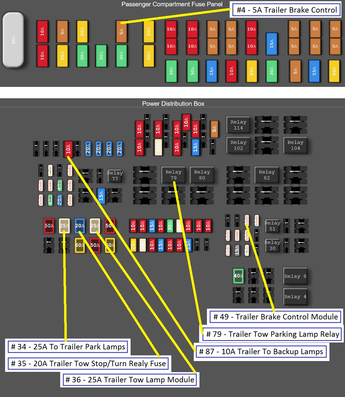
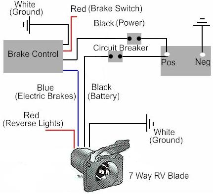
5 wire trailer wiring diagram. Electric hydraulic brake actuator works with your brake controller sold separately to activate your trailers disc brakesvented housing releases heat and moisture.

2008 F350 Trailer Wiring Harness Diagram H1 Wiring Diagram
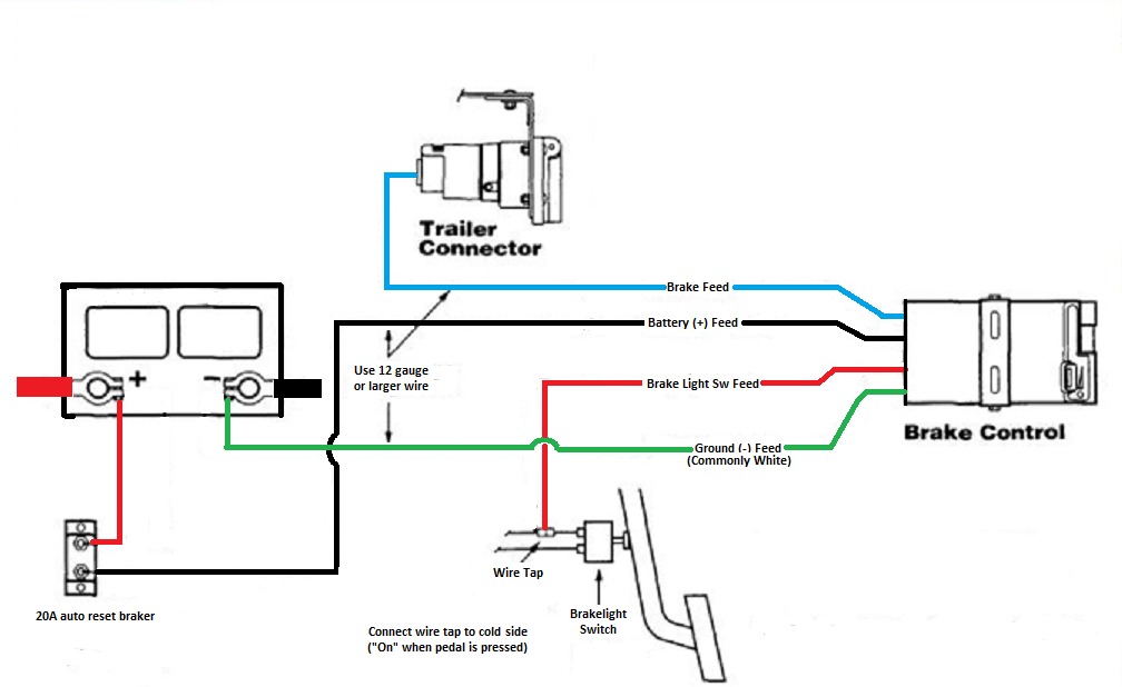
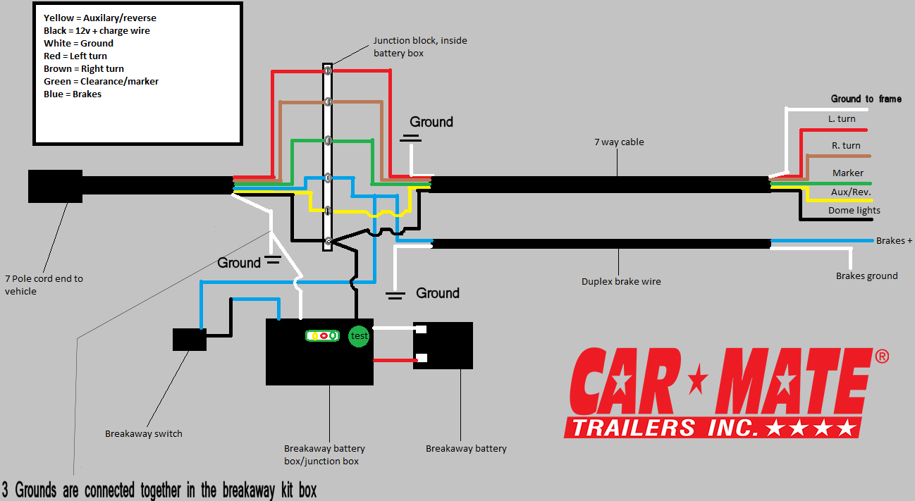
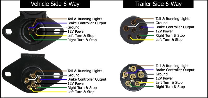
Trailer brake wiring harness diagram. An extra pin allows using another extra function. Trailer connectors are used between the two to allow disengagement when not. Complete with a color coded trailer wiring diagram for each plug type this guide walks through various trailer wiring installation solution including custom wiring splice in wiring and replacement wiring. 5 way trailer wiring diagram allows basic hookup of the trailer and allows using 3 main lighting functions and 1 extra function that depends on the vehicle. If your vehicle is not equipped with a working trailer wiring harness there are a number of different solutions to provide the perfect fit for your specific vehicle. By law trailer lighting must be connected into the tow vehicles wiring system to provide trailer running lights turn signals and brake lights.
The following trailer wiring diagrams and explanations are a cross between an electrical schematic and wiring on a trailer. Single tandem and triple axle trailers with disc brakes maximum output pressure. And connects to trailers wiring and hydraulic brake lines sold separately made in the usa specs. Various connectors are available from four to seven pins that allow for the transfer of power for the lighting as well as auxiliary functions such as an electric trailer brake controller backup lights or a 12v power supply for a winch or interior trailer lights. This is accomplished by tapping into the tow vehicles electrical harness to transfer power to the trailer wiring system. We recommend these standards because they are pretty universal.
Enhanced wiring protection. Trailer wiring diagrams trailer wiring connectors. That said for specific situations there are industrial standards with different connectors and wire arrangements.


