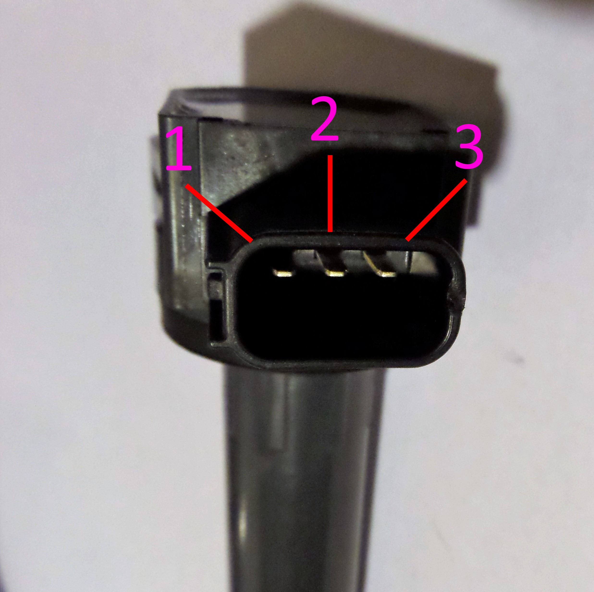
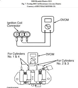
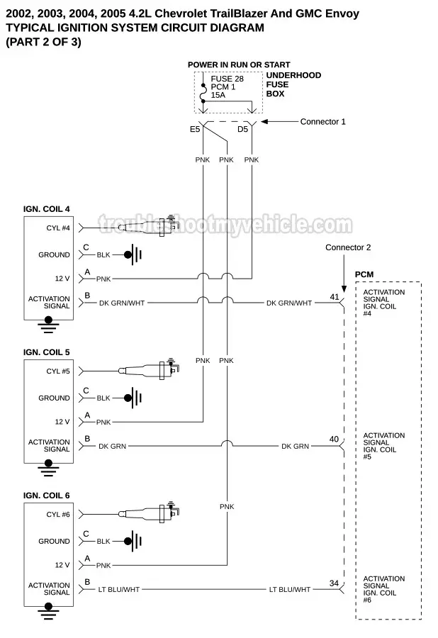
A 4 wire cop has the following connections pin numbers may vary depending on the type of coil. What are three wire smart coil on plugs.

9n Ford Tractor 12 Volt Wiring Diagram Wiring Diagram
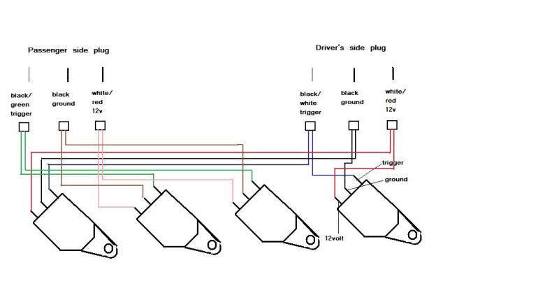
3 wire coil on plug diagram. This full time ground wire is for the transistor ignition module itself. Now that we have learned the purpose of each wire in this type of coil on plug lets jump into the actual tests. Here are the step by step tests for testing the majority of the coil on plug ignition systems that have ignition coils with three wires circuits in the connector. I need a diagram of the spark plug layout on a f l engine w ac. Trigger typically a 5 v active high pulse from the ecm to the coil. Just trying to get an answer to this question.
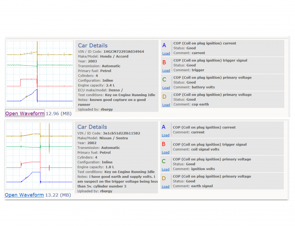
The delphi training series breaks it down for you. Positive supply switched battery voltage. Connect picoscope channel c to the coil voltage supply. The wired differences matt dixon southern illinois university carbondale. Coil pack plugford f the diagram for spark plug wiresl. The check engine light came on the code indicates the 4 cylinder is misfiring.
The coil pack towers are numbered. So whether its a ford a chevrolet a mazda a suzuki a mitsubishi or whatever in the usa or europe or south or central america or where ever on the planet these easy tests work. Cylinder to cylinder variations are valuable. Primary current is an available test on all types. Use manufacturer data to identify the function of the three coil terminals. I checked the 4 spark plug and wire.
Feedback typically a 5 v active low pulse from the coil to the ecm. How to perform the test. Coil on plug ignition. This coil on plug ignition coil with the three wires in the connector has the ignition module integrated into the coil itself. Connect picoscope channel b to the coil signal terminal. Groundearth battery negative.
Does anyone know where i can find a wiring diagram on the net for coil on plug coils. Ignition coil test for coil on plug systems duration. Connect the low amp clamp to picoscope channel a select the 20 a scale and zero the clamp before attaching to the coil voltage supply terminal. Garage gurus 41046 views. 23 and 4 wire coil versions are different in control monitoring strategies. On the loom i have there are 4 wires in each cop plug brownyellow common earth which bolts on the cam cover thin black wire the coloured tracer assuming this is the trigger wire then a brown wire and a blackpurple wire one i guess is 12v supply dont know which and what is the other.
View connection guidance notes.


