Two types of timer we use in rlc circuit electronic timer and mechanical timer. Clap switch circuit using ic 555 timer without timer.
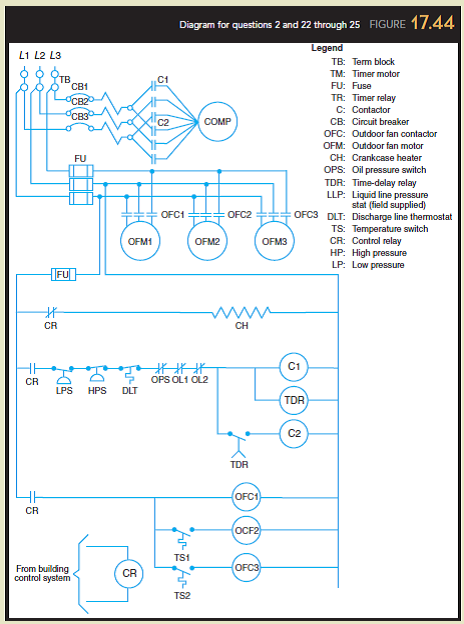
Solved Diagram For Questions 2 And 22 Through 25 Figure 1
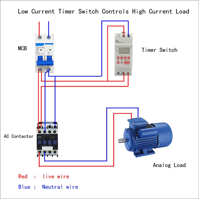
Timer contactor diagram. 240 volts ac and 480 volts ac are commonly used for these large pieces of. Timer has two element timer and relay. On delay timer circuit diagram wiring diagram contactor with push button circuit diagram of delay timer on off power off delay timer circuit diagram 2 way lighting circuit triggering transformer push button fan switch light activated switch circuit diagram wd081 text. The on delay timer diagram is also shown in the diagram. Iec contactor specifications bulletin numbers 100104 k 100104 c 100104s c 100104 e 100s e 100104 d 100s d 100 g 100q c topic page. Contactor wiring diagram with timer datasheet.
When we give supply to timer timer run and after completing set time t timers relay on. With this kind of an illustrative guidebook you will be capable of troubleshoot prevent and complete your projects without difficulty. In control wiring diagram all magnetic contactors coils are rated 220 vac. How to wire a contactor. These lines far exceed the 120 volts ac standard in most homes. All panels are pre wired and ul listed complete with a nema 1 enclosure wiring diagram terminal connection block timer timer panels and two or four 3 pole contactors.
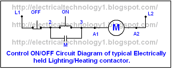
Many large pieces of equipment are powered directly from high voltage lines. Contactor wiring diagram you will want a comprehensive professional and easy to know wiring diagram. One line diagram of simple contactor circuit control onoff circuit diagram of typical electrically held lightingheating contactor a contactor is an electr. Electrical earthing methods and types of earthing grounding. Each component should be placed and linked to other parts in particular manner. With help of following timing diagram we can easily understand working of timer.
A 8 pin timer are used. A simple circuit diagram either of the two start buttons will close the contactor either of the stop buttons will open the contactor. Clap switch circuit using ic 555 timer without timer. Many large pieces of equipment are powered directly from high voltage lines. The danfoss contactor and timer panels are primarily designed for snow and ice melting applications. Electrical earthing methods and types of earthing grounding.
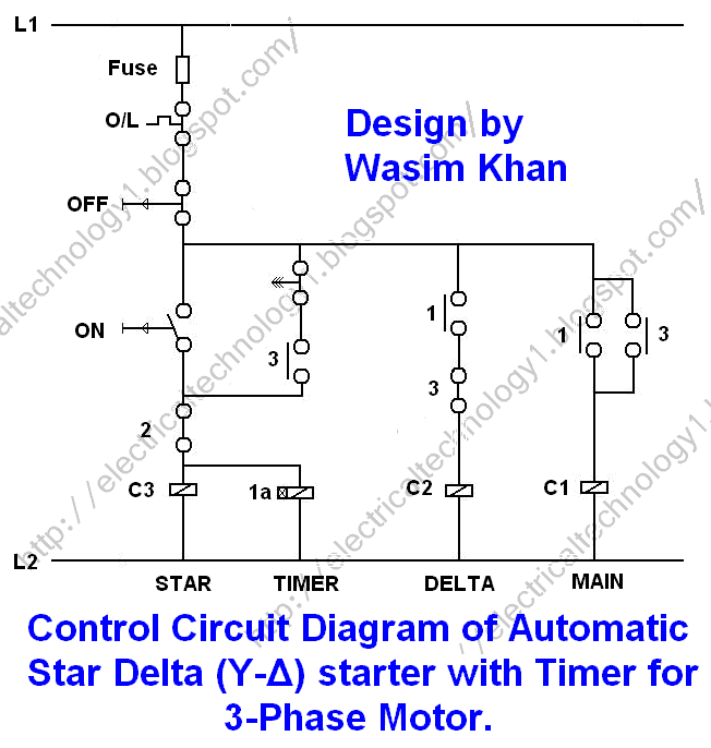
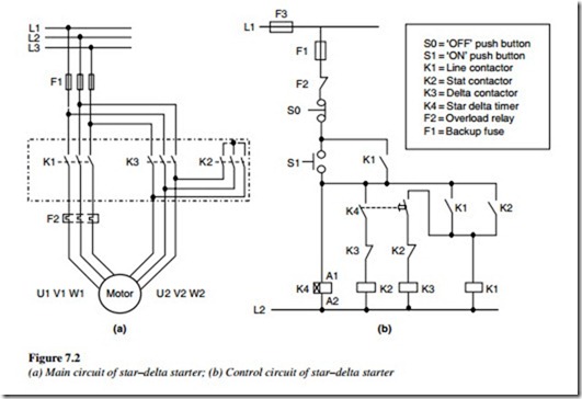
In the above star delta starter control circuit wiring diagram with timer and normally close push buttonnormally open push button switch. Timimng diagram of timer. Direct online starter animation diagram.


