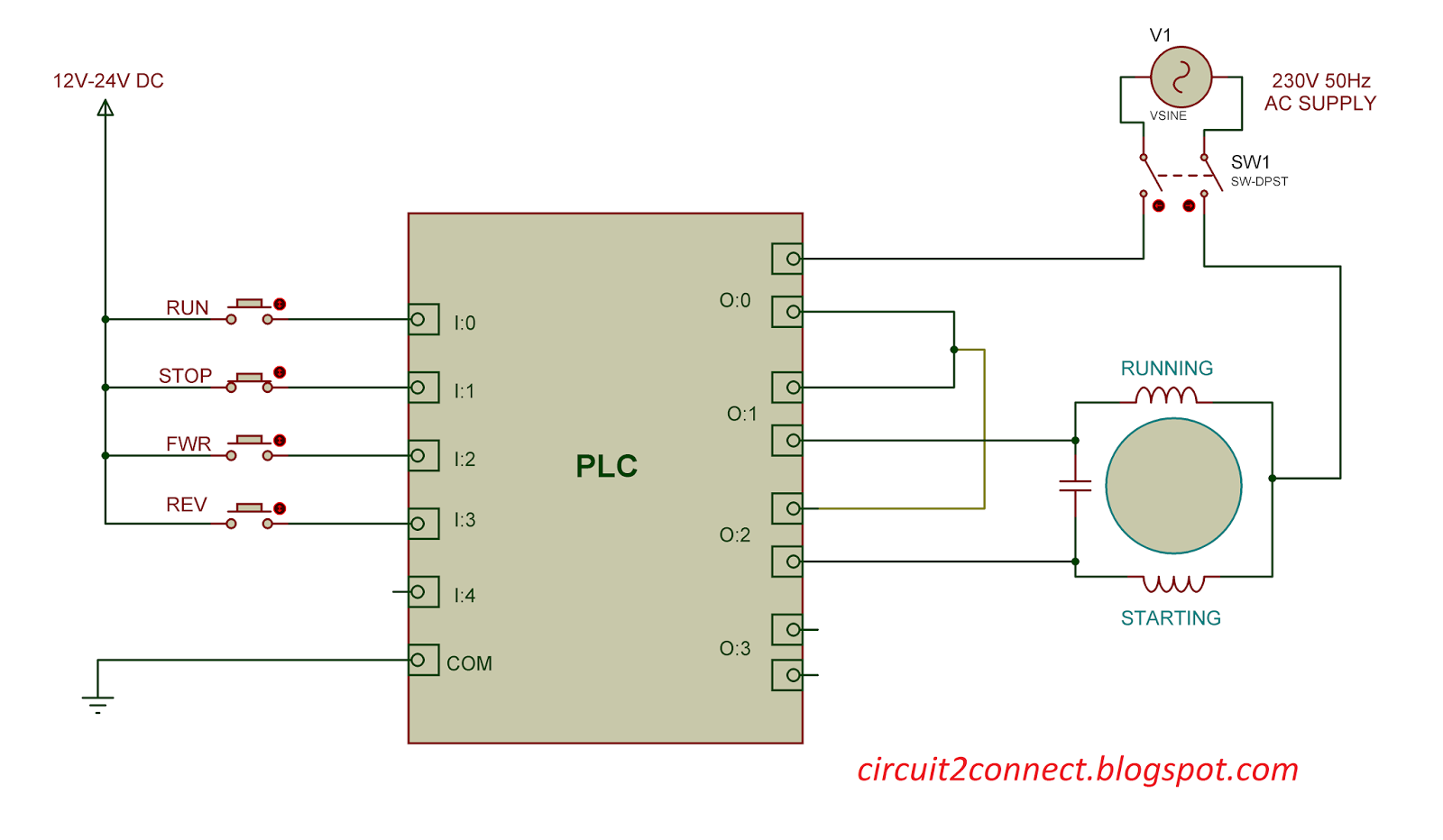
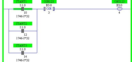
In the following example a normally open start pushbutton is wired to the first input i00 a normally closed stop pushbutton is wired to the second input i01 and normally closed overload relay contacts part of the motor starter are connected to the third input i02. The above figure shows the physical layout of motor starter however this would be designed through ladder logic in this plc tutorial.
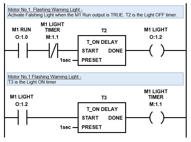
Plc Timer Ladder Logic World
Motor control circuit diagram with plc. Today i will walk you through programming a very basic stop start circuit for an electric motor. When including a plc in the ladder diagram still remains. Figure 5 below shows a schematic diagram for a plc based motor control system similar to the previous motor control example. But it does tend to become more complex. Above figure does not show limit switch because it depends on external interlock like say level switch flow switch pressure switch etc depending on application. Introduction to plc ladder diagrams.
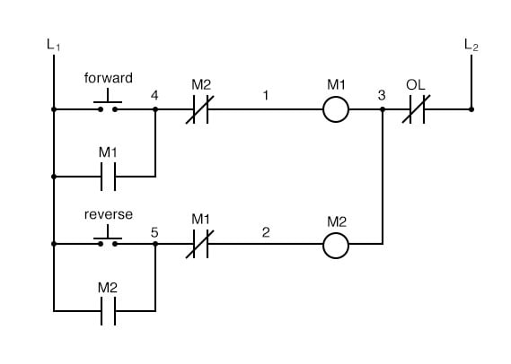
If we wanted to keep the motor running even after the operator takes his or her hand off the control switches we could change the circuit in a couple of different ways. This figure shows the e stop wired to cutoff power to all of the devices in the circuit including the plc. The interlock contacts installed in the previous sections motor control circuit work fine but the motor will run only as long as each push button switch is held down. However if you take your time and learn the basics it can be an easily achievable task. If interlock not required then simply remove the symbol from the diagram and connect with simple. We could replace the push button switches with.
As an introduction to ladder diagrams consider the simple wiring diagram for an electrical circuit in figure 1athe diagram shows the circuit for switching on or off an electric motor. This motor control application can also be accomplished with a plc. Upgrading a machine to plc control may seem like a daunting task.


