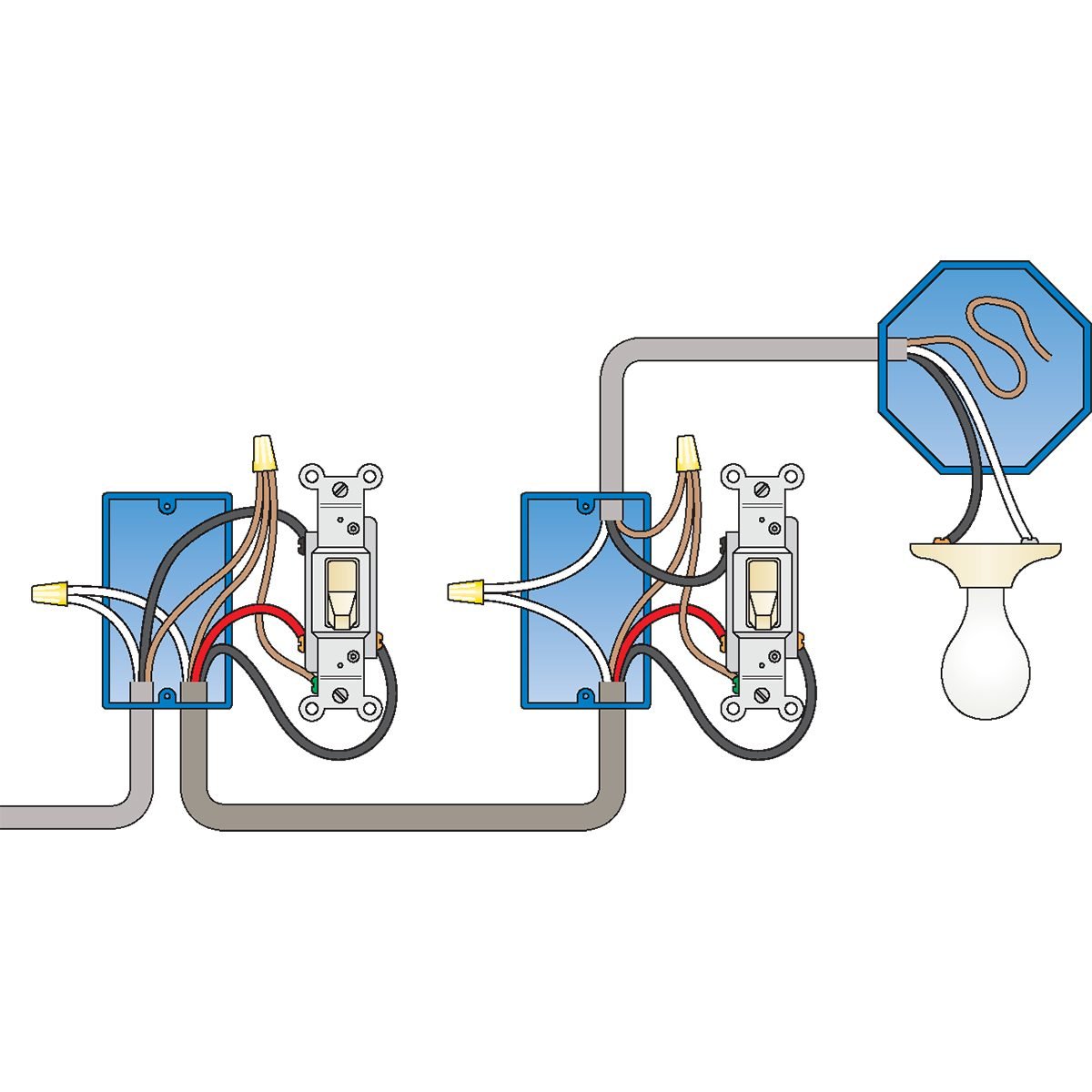
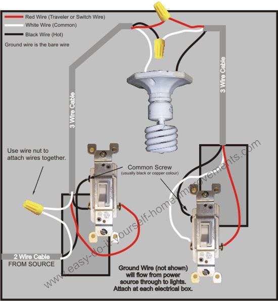
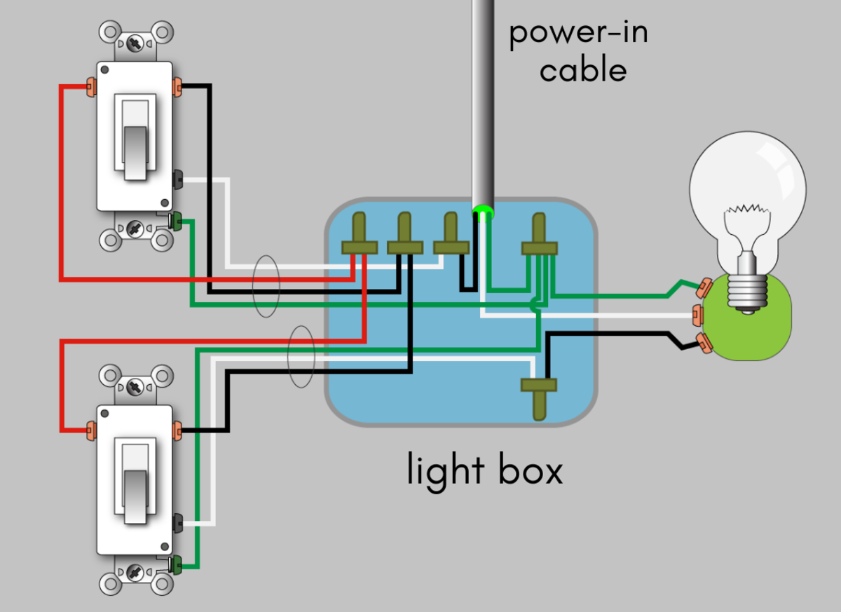
Three way switches 2 wiring a 3 way light switch. The source is at sw1 and 3 wire cable runs between all the devices.
Wire An Outlet
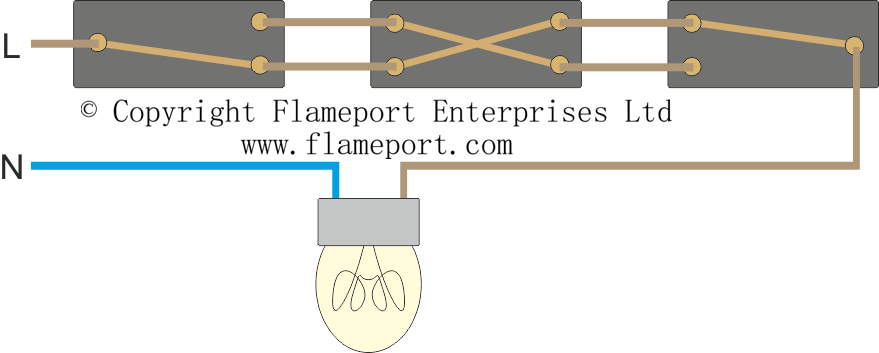
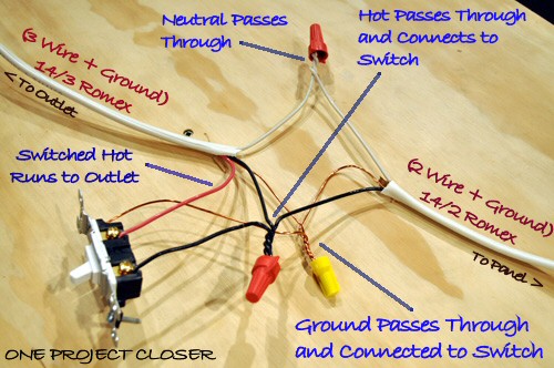
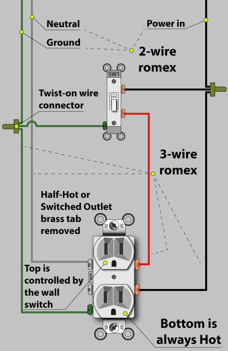
Three way switched outlet diagram. No longer allowed after 2011 nec if no neutral wire in switch boxes 3 way switch wiring diagram light fixture between switchesline voltage enters the first 3 way switch outlet box light fixture is located between switch boxesno longer allowed after 2011 nec if no neutral wire in switch boxes. Notice that these outlets have the tab removed from the hot side or brass side of the outlet which allows the top half of the plug to be controlled only from the switch. Below is a simple 3 way schematic that can be applied to all three way electrical light switch connections. At the outlets each is wired using a pigtail splice to make the hot and neutral connections. Here is a diagram of how this receptacle could be added in the proper circumstance. Two very old three way switches are depicted in the photo above.
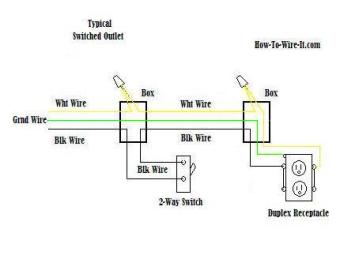
Terry peterman the internet electrician provides a visual explanation of the basic 3 way switch in this short informative video. The source for the circuit is at the switch and 2 wire cable runs to each receptacle outlet. 3 way switch schematic wiring diagram. Buy a single pole switch if one switch controls the lights or a three way if you have two switches controlling the same lights. Two very old three way switches. This diagram shows the wiring arrangement for a 3 way switched outlet.
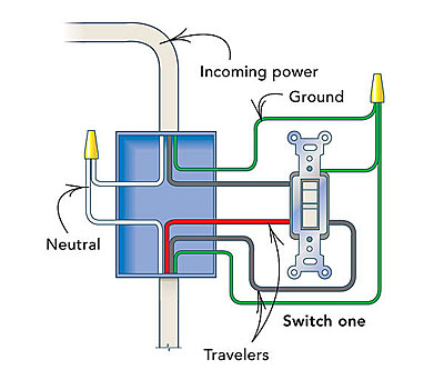
Switched outlet diagram with hot and a neutral entering the switch box. Wiring a 3 way light switch is certainly more complicated than that of the more common single pole switch but you can figure it out if you follow our 3 way switch wiring diagram. 3 way switched outlet wiring diagram. 3 way switch wiring diagram line to light fixtureline voltage enters the light fixture outlet box. Wiring diagram for multiple switched outlets. This diagram shows the wiring for multiple switched outlets on one switch.
Standard and halogen bulbs require standard incandescent dimmers. With this wiring the receptacle can be controlled from two locations. A two conductor cable is installed from the switched outlet to feed an outlet that is live at all times. With a pair of 3 way switches either can make or break the connection that completes the circuit to the light. Confused by the 3 way switch. The diagram below shows the power entering the circuit at the grounded outlet box location then sending power up to the switch and a switched leg back down to the outlet.
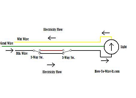
Watch a video explaining 3 way switches. A few fluorescent lights can be dimmed with special dimmer switches but most cant. Click here to view. From there a 3 conductor cable is installed to a switched electrical receptacle outlet. This is only a wiring schematic and not the actual wiring method used for 3 way switch installations. In the wiring diagram above a hot and a neutral enter the single pole switch box.

