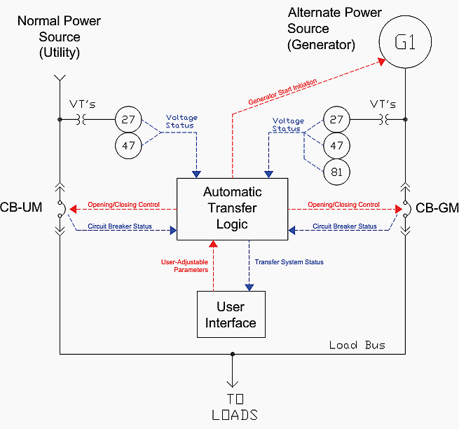
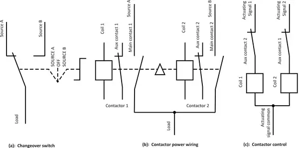
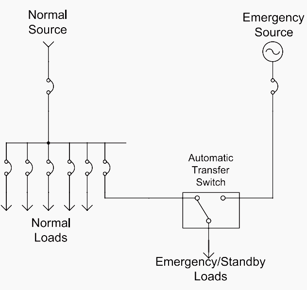
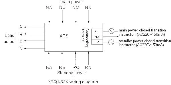
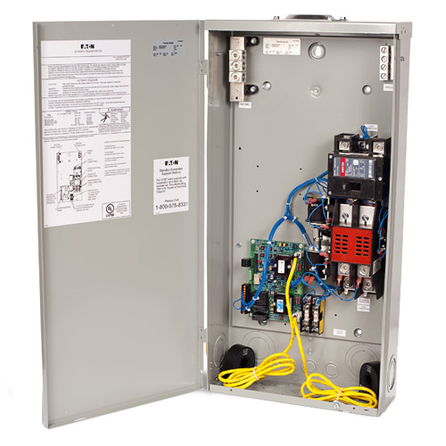
It is only to automatically turn off generator and shift to gridautomatic change over is used to shift from generator to grid and relay is used only to turn off generator. A contactor when closed opens its own auxiliary contact.
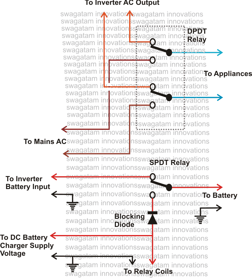
2 Easy Automatic Inverter Mains Ac Changeover Circuits
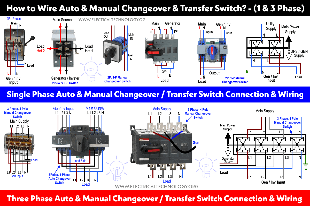
Simple automatic changeover switch circuit diagram. This contact being in series with the coil of the other contactor will not allow the other contactor to close. 2 simple automatic transfer switch ats circuits. Please im requesting for a circuit diagram of auto starter. It is also shows the working and operation for different changeover switches wiring connections like single phase manual changeover switch with generator three phase manual transfer switch connection with generator as well as single phase and three phase automatic transfer switches connections to the 1 and 3 phase generators and main fuse board. The circuit diagram shown here is of a automatic changeover switch using ic ltc4412 from linear technologies. Here we use the simple logic that when trigger pin is grounded output is a high logic signal and when reset pin is grounded output is low logic signal.
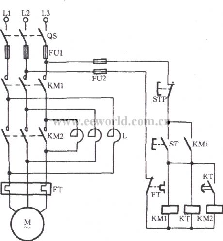
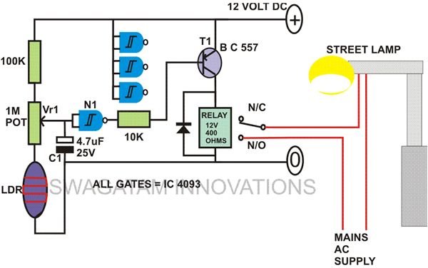
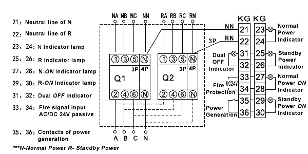
Automatic changeover switch circuit diagram. Ups relay changeover circuit. In this automatic changeover switch for generator circuit diagram the contactors of the generator are indicated kg and km. The next concept makes an attempt to create a simple relay changeover circuit with zero crossing detector which may be used in inverter or ups changeover applications. Here the output of 555 timer is connected to the base of transistor bc547. A system using automatic change over and a relay.
This circuit can be used for the automatic switchover of a load between a battery and a wall adapterltc4412 controls an external p channel mosfet to create a near ideal diode function for power switch over and load sharing. This could be used for switching over the output from ac mains to inverter mains during inappropriate voltage conditions.

