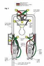
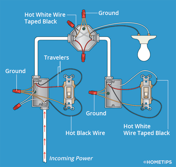
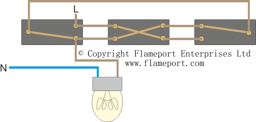
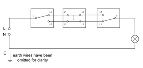
With these diagrams below it will take the guess work out of wiring. A wiring diagram is a simplified conventional photographic depiction of an electric circuit.

Single Pole Switch Vs Three Way Switch Differences Between Single Pole And 3 Way Switch
Three way circuit diagram. Wiring a 3 way light switch is certainly more complicated than that of the more common single pole switch but you can figure it out if you follow our 3 way switch wiring diagram. In this diagram the electrical source is at the first switch and the light is located at the end of the circuit. A 4 way switch must be wired between two 3 way switches as shown in the diagrams on this page. This might seem intimidating but it does not have to be. Three wire cable runs between the switches and 2 wire cable runs to the light. Turn the power off at circuit breaker.
Three way switches can be wired in a number of different ways depending on where they are located relative to the light fixture in the circuit cable runs. Below is a simple 3 way schematic that can be applied to all three way electrical light switch connections. The black and red wires between sw1 and sw2 are connected to the traveler terminals. 3 way switch wiring diagram line to light fixtureline voltage enters the light fixture outlet box. Two very old three way switches are depicted in the photo above. Wiring diagram 3 way switch with light at the end.
3 way switch wiring diagram. A 4 way switch has five terminals. For example they can be arranged so that the feed cable runs to the first three way switch then to the light fixture box then to the second three way switch. It shows the elements of the circuit as streamlined shapes and the power and also signal links in between the devices. Each pair of traveler terminals should be wired to the traveler wires from one of the 3 way switches in the circuit. One ground and 4 circuit terminals divided into two matching pairs called travelers.
3 way switch schematic wiring diagram. Basic 3 way switch diagram how to wire 3 way light switch step by step. The first step in any electrical project is to make sure there is no power going to the circuit you plan to be working on. The goal is to place two switches at separate locations which control the exact same device. Assortment of fender telecaster 3 way switch wiring diagram. This is only a wiring schematic and not the actual wiring method used for 3 way switch installations.
You must completely forget about the notion of a switch being a simple openclosed circuit and look at the diagram of the circuitry of this modern alternative. With a pair of 3 way switches either can make or break the connection that completes the circuit to the light. Wiring a 3 way light switch. Pick the diagram that is most like the scenario you are in and see if you can wire your switch. Take a closer look at a 3 way switch wiring diagram. No longer allowed after 2011 nec if no neutral wire in switch boxes 3 way switch wiring diagram light fixture between switchesline voltage enters the first 3 way switch outlet box light fixture is located between switch boxesno longer allowed after 2011 nec if no neutral wire in switch boxes.
A three way switch is fundamentally different in its operation from a regular two way switch. Two very old three way switches.


:max_bytes(150000):strip_icc()/Three-waySwitchDiagramNew400-56a27f6a3df78cf77276b609.jpg)


