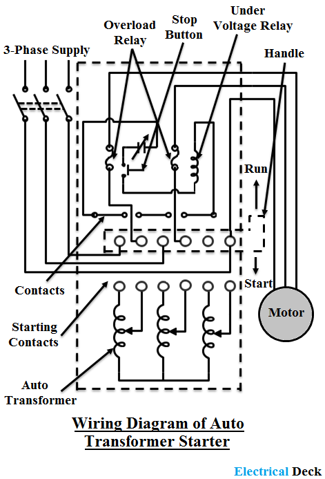
That being said there is a wide range of different motors and what you have on hand can be completely different. For all other single phase wiring diagrams refer to the manufacturers data on the motor.

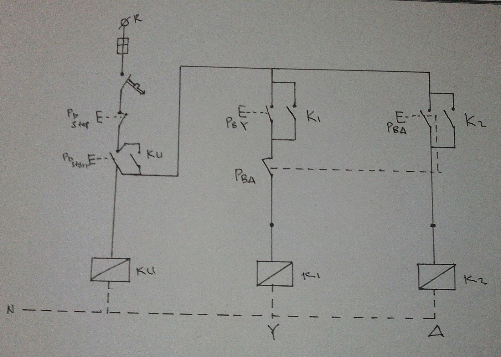
Tk 9464 Wiring Diagram Of Star Delta Starter How To
Three phase induction motor wiring diagram. The first step is to figure out the voltage of your phases. Diagram dd6 diagram dd7 m 1 ln e diagram dd8 ln e l1 l2 l3 sc z1 u2 z2 u1 cap. This type of motor is designed to provide strong starting torque and strong running for applications such as large water pumps. Difference is that transformer is an alternating flux machine while induction motor is rotating flux machine. Motorsone two and three phase. The alternating current windings of three phase alternating current generators and synchronous motors shall have terminal markings as given in mg 1 261 for three phase single speed induction motors the alternating current windings of two phase alternating current generators and synchronous motors.
This video explains how to wire a three phase induction motor to an external electricity source. Three phase motor connection stardelta y δ reverse forward with timer power control diagram starting stopping of 3 phase motor from more than one place power control diagrams control 3 phase motor from more than two buttons power control diagrams. Capacitor start induction motor csim circuit wiring diagram and torque speed curve. In the 3 phase motor forward reverse starter wiring diagram. Thermal contacts tb white m 1 z2 yellow z1 blue u2 black u1 red bridge l1 and l2 if speed controller sc is not required m 1 ln e white brown blue l1 l2 n sc. Three phase wiring diagrams always use wiring diagram supplied on motor nameplate colored leads are only applicable on the new rolled steel motor lines single phase wiring diagrams always use wiring diagram supplied on motor nameplate for motors with thermal protection.
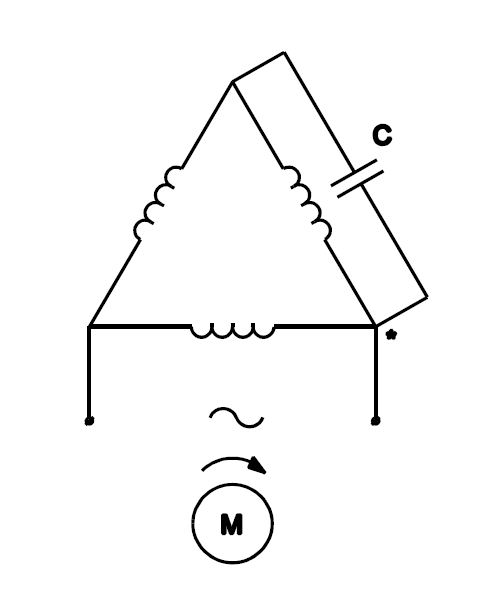
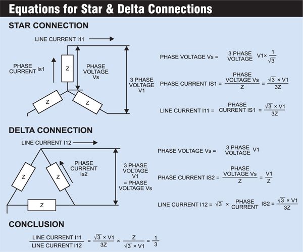
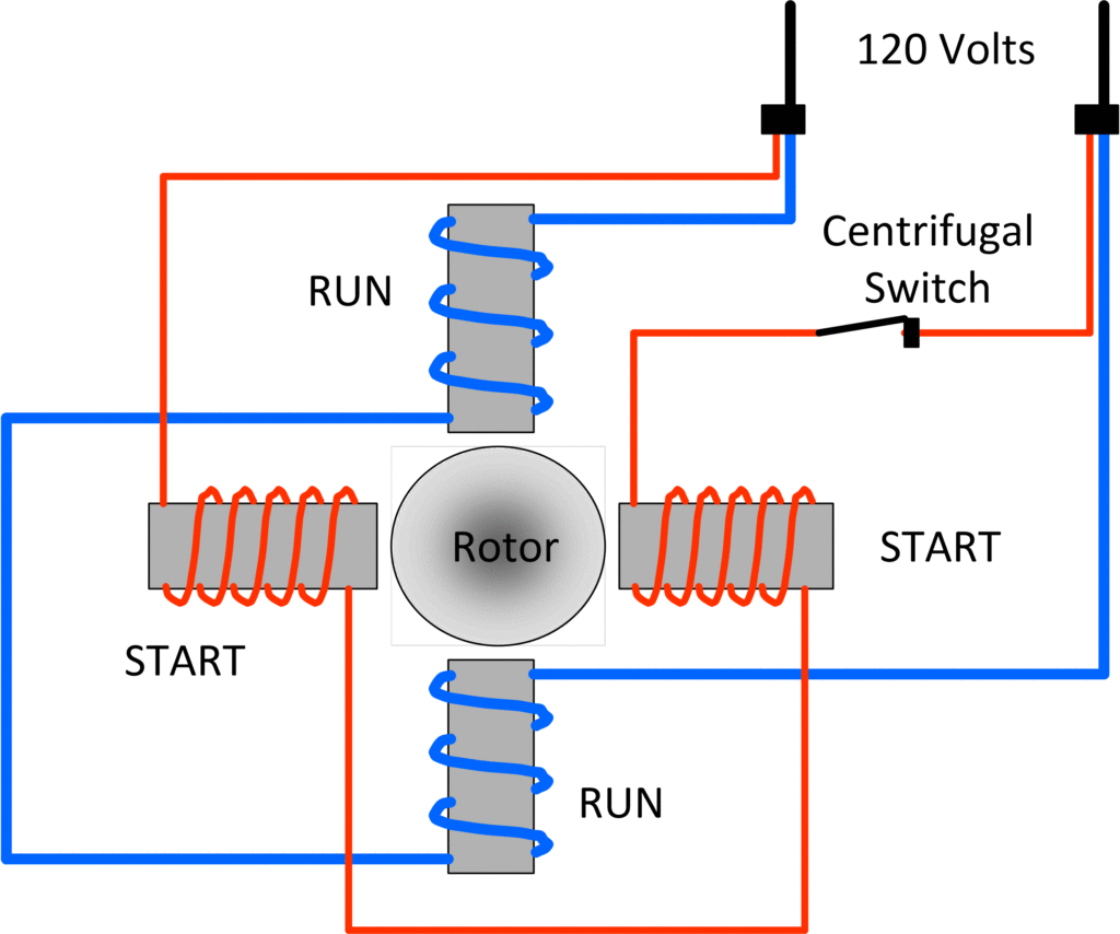
Capacitor start capacitor run induction motors are single phase induction motors that have a capacitor in the start winding and in the run winding as shown in figure 12 and 13 wiring diagram. Single phase motors are inherently noisier and less smooth running than polyphase motors. In the united states for low voltage motors below 600v you can expect either 230v or 460v. Induction motor is a generalized transformer. It also shows the difference between delta and star connections used to connect the motor coils. Rotating flux is only possible when 3 phase voltage or poly phase which is 120 degree apart in time is applied to a three phase winding or poly phase winding 120 degree apart in space then a three phase rotating magnetic flux is.
Because there is a backward rotating component of flux there are pulsating torques so the torque speed curve is really just a representation of the average. A three phase motor must be wired based on the diagram on the faceplate. In short this the complete guide of forward reverse starter. I shown the 3 pole mccb circuit breaker 2 magnetic contactor normally open normally close push button switch thermal overload relay 3 phase 4 wire system supply 3 phase motor with connection trip indicator light etc.





.png)

