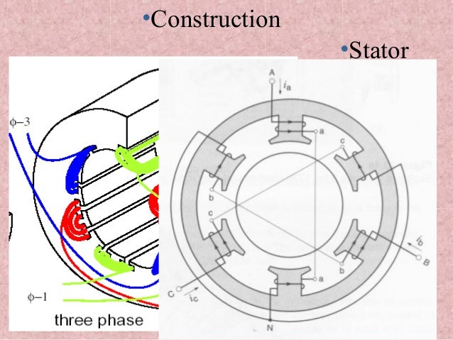
Rotating flux is only possible when 3 phase voltage or poly phase which is 120 degree apart in time is applied to a three phase winding or poly phase winding 120 degree apart in space then a three phase rotating magnetic flux is. Test performed to compute data required for drawing circle diagram.
Types Of Three Phase Induction Motor Rotor Javatpoint
Three phase induction motor diagram. In two pole single phase motors the torque goes to zero at 100 slip zero speed so these require alterations to the stator such as shaded poles to provide starting torque. In this test the motor runs at the rated supply voltage without any load so there. An electrical motor is an electromechanical device which converts electrical energy into mechanical energy. Difference is that transformer is an alternating flux machine while induction motor is rotating flux machine. Split phase single phase shaded pole single phase and polyphase. A single phase induction motor requires separate starting circuitry to provide a rotating field to.
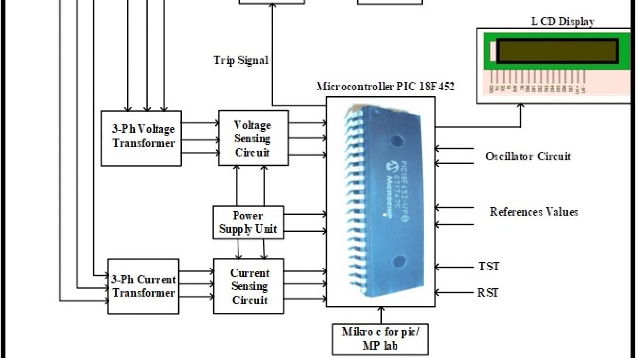
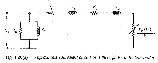
The input power given to an induction motor is in the form of three phase voltage and currents. In the united states for low voltage motors below 600v you can expect either 230v or 460v. Single phase induction motors are used in residential applications for ac motor appliances in single or multiple dwellings. Induction motor is a generalized transformer. Therefore an induction motor may be considered to be a transformer with a. The energy is transferred magnetically from the stator winding to the short circuited rotor winding.
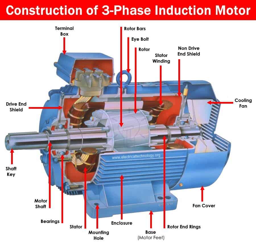
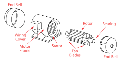
There are three basic types of small induction motors. There are three types of single phase induction motors which are the shaded pole split phased and capacitor. The power flow diagram of an induction motor is shown below. The three phase induction motor is the most widely used electrical motoralmost 80 of the mechanical power used by industries is provided by three phase induction motors because of its simple and rugged construction low cost good operating characteristics the absence of commutator and good speed regulation. Phasor diagram of three phase induction motor. In the case of three phase ac alternating current operation the most widely used motor is a 3 phase induction motor as this type of motor does not require an additional starting devicethese types of motors are known as self starting induction motors.
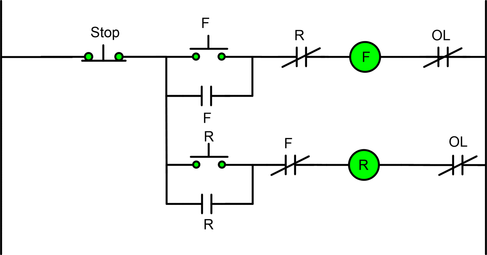
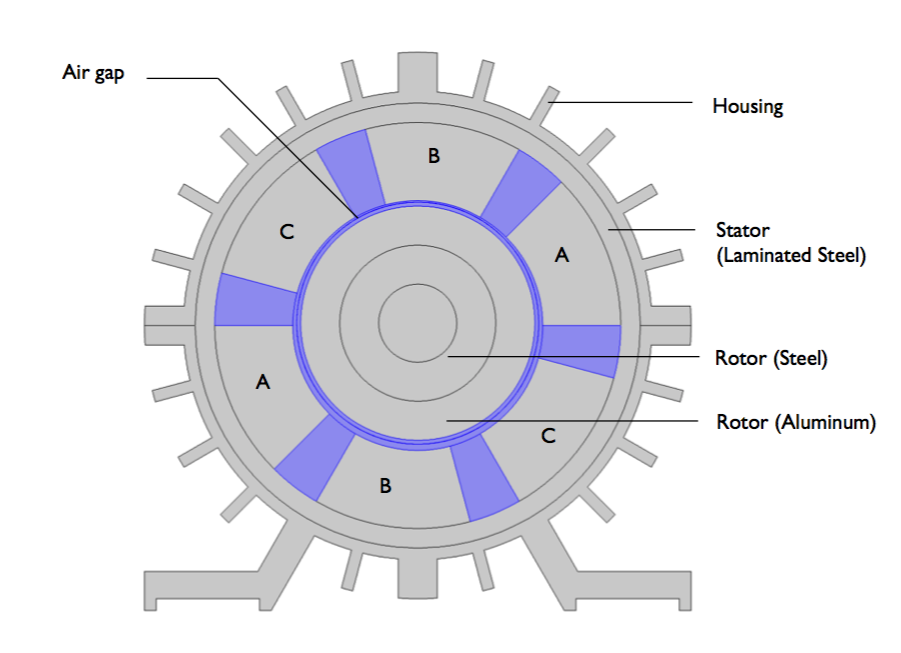
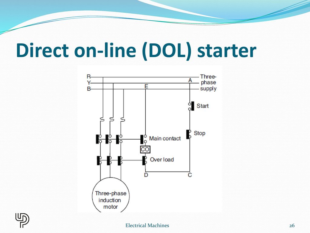
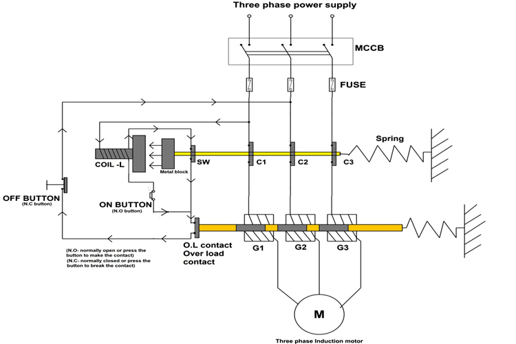
A three phase motor must be wired based on the diagram on the faceplate. The three phase supply current produces an electromagnetic field in the stator winding which leads to generate the torque in the rotor winding of three phase induction motor having magnetic field. In a 3 phase induction motor the stator winding is connected to 3 phase supply and the rotor winding is short circuited. A single phase induction motor is an electric motor that operates on a single waveform of alternating current. That being said there is a wide range of different motors and what you have on hand can be completely different. The diagram is also easier to remember and understand compared to the theoretical and mathematical description.
Power flow diagram and losses of induction motor power flow diagram of induction motor explains the input given to the motor the losses occurring and the output of the motor. The first step is to figure out the voltage of your phases. In three phase induction motor the power is transferred from stator to rotor. To draw the circle diagram of induction motor we do three tests. A three phase induction motor is a type of ac induction motors which operates on three phase supply as compared to the single phase induction motor where single phase supply is needed to operate it.
