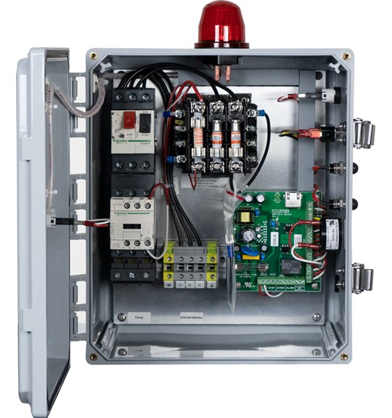
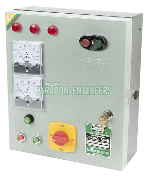
Single phase power is commonly called. Incepted in the year1990 umiya electric is an eminent name in the field of manufacturing and supplying of all types of panel boards like growler rotor testing panel single phase control panel.
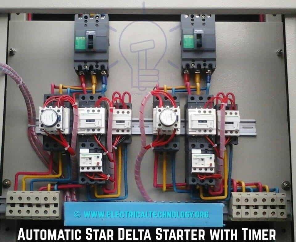
Star Delta Starter Y D Starter Power Control And Wiring
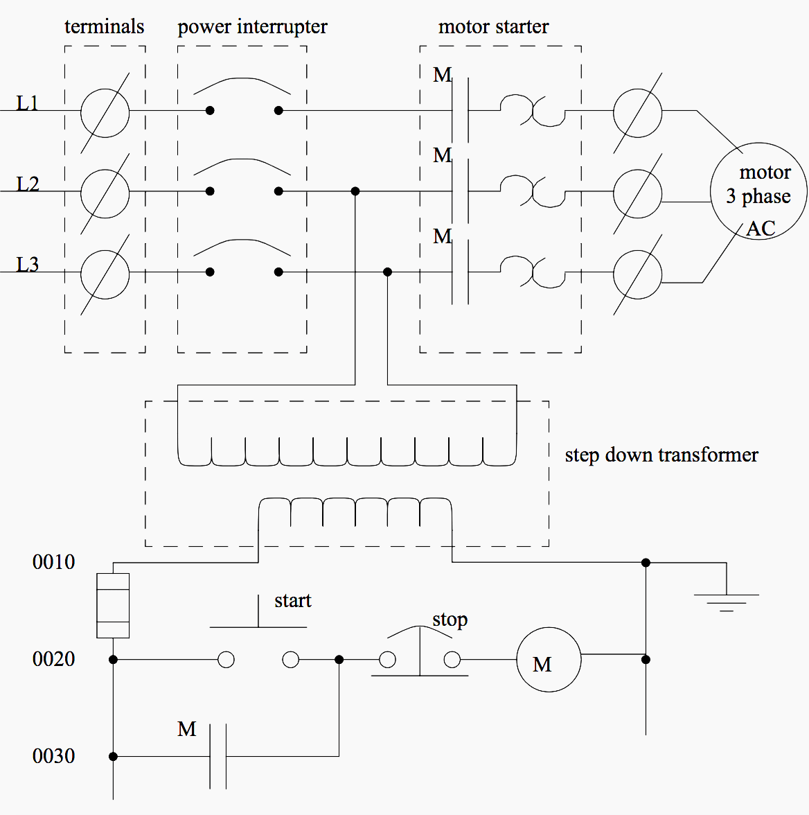
Three phase control panel wiring diagram. This is a start stop push button control schematic which includes contactor m overload relay control transformer and push buttons. The difference between three phase and single phase is primarily in the voltage that is received through each type of wire. Phase 2 l1 l2 l3 ground when used. The wiring diagram for connecting thee phase motor to the supply along with control wiring is shown in figure below. Star delta y δ 3 phase motor starting method by automatic star delta starter with timer. Phase 1 l2 l4.
It reveals the components of the circuit as streamlined forms and the power and signal links in between the tools. There is no such thing as two phase power which is a surprise to some people. Here i showed the forward reverse wiring diagram. Why we called a single phase submersible motor a 3 wire submersible that we also know that we have two wire in single phase power supply. Collection of onan generator wiring diagram. Three phase motor connection stardelta without timer power control diagrams.
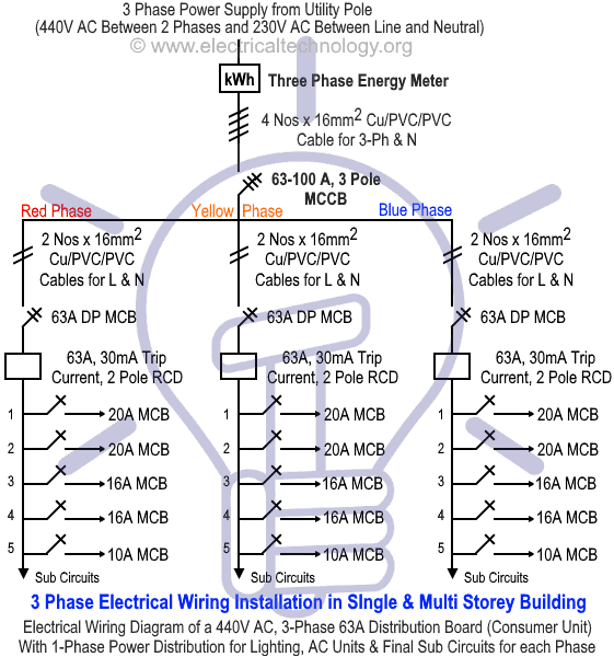
Forward reverse motor control diagram for three phase motor for three phase motor forward reverse control circuit. The difference between single phase three phase electrical wiring. A wiring diagram is a simplified traditional pictorial depiction of an electric circuit. The phase voltage is lower than line voltage in star connection so the motors or drives connected in star connection runs at lower speed as compared to delta connection. Three phase motor connection schematic power and control wiring installation diagrams. We use 2 magnetic contactors as forward reverse switch.
In the diagram i connect the incoming three phase supply l1 l2 l3 to the mccb circuit breaker molded case circuit. Today i am hear to write about submersible pump control box wiring diagram in this post you will complete understood about 3 wire submersible pump wiring diagram which is an single phase submersible pump motor. Typical controller markings typical elementary diagram iec typical controller markings typical elementary diagram table 4 control and power connections for across the line starters 600 v or less from nema standard ics 2 321a60 1 phase 2 phase 4 wire 3 phase line markings l1 l2 l1 l3. In this tutorial we will show the star delta y δ 3 phase induction ac motor starting method by automatic star delta starter with timer with schematic power control and wiring diagram as well as how star delta starter works and their applications with advantages and disadvantages.


