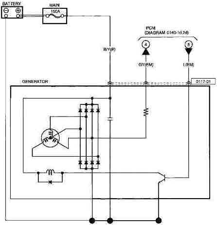
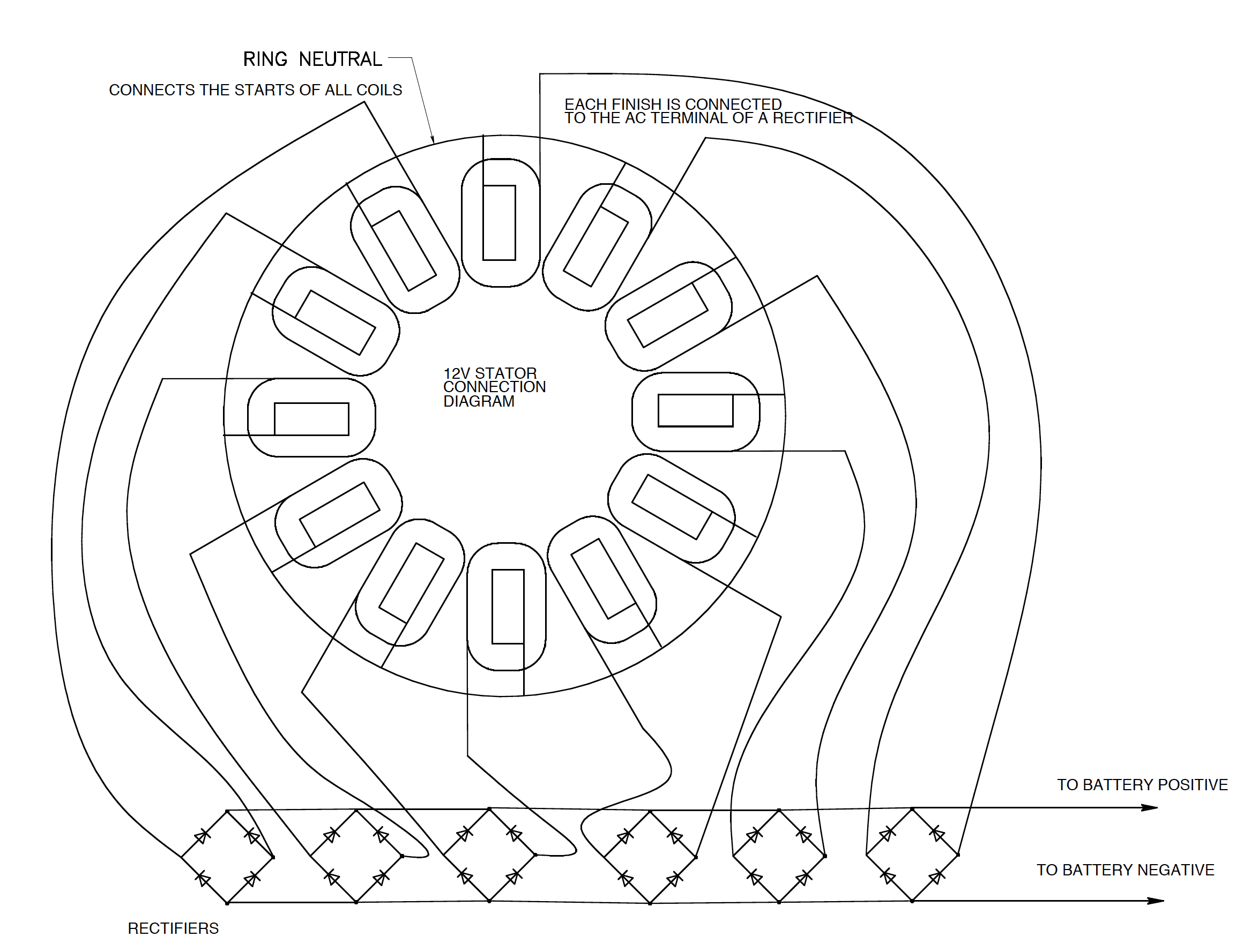
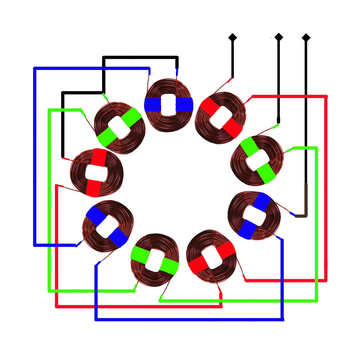
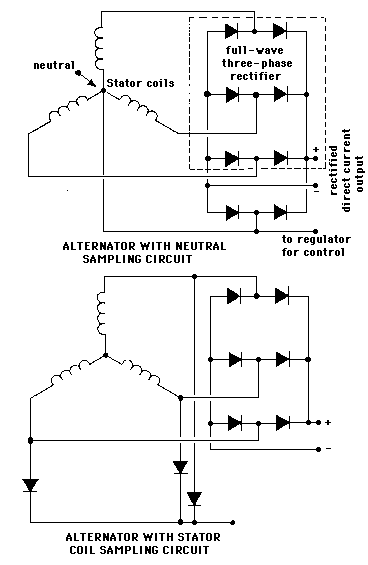
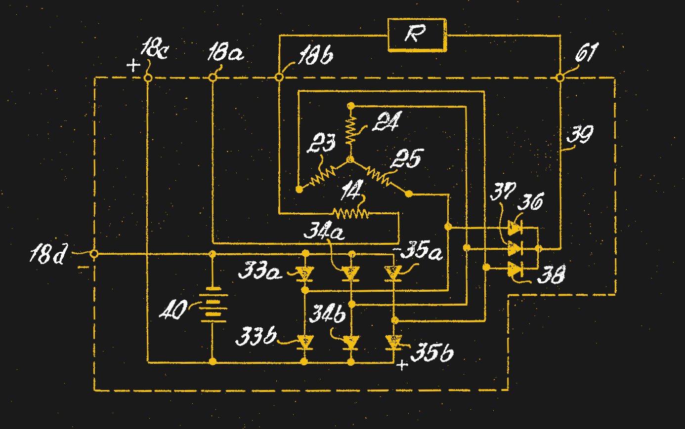
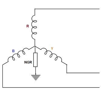
The diagram below showcases different variations of load connected to the three phase system. Instead of being connected at the output terminals the b1 a2 connection was made internally when the stator was wired.

Automotive Alternator Ac Circuits Electronics Textbook
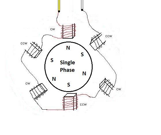
3 phase alternator connection diagram. 3 10 now look at the smaller schematic diagram in figure 3 7. A two phase alternator connected in this manner is called a two phase three wire alternator. It is called a wye connection because without the neutral the windings appear as the letter y in this case sideways or upside down. The simplified schematic of figure 3 8 view a shows all the windings of each. The neutral connection is brought out to a terminal when a single phase. In a single phase unit the power falls to zero three times during each cycle in 3 phase it never drops to zero.
Besides a high pickup capacity motors startup. 3 tio til t4 t5 t12 ti blu t2 wht t3org t4 yel t5 blk t6 gry t7 pnk t8 red t9 brk red tio curry tii grn t12 vlt z t4. These connections can be star or delta depending on the secondary of the distribution transformer. The consumers are the loads connected to the electrical system. Only three connections have been brought out from the stator. Generators should be derated by 13 of their original capacity.
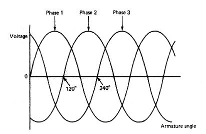
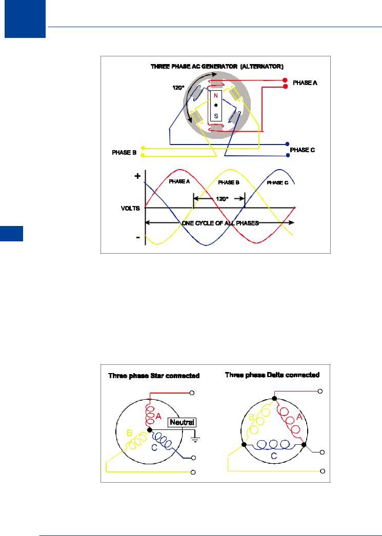
Rather than having six leads coming out of the three phase alternator the same leads from each phase may be connected together to form a wye y connection as shown in figure 1 view b. U n w w2 w6 v6 w1 v2 w5 u1 u2 u5 u6 v1 v v 240v 12 lead double delta. The three phase alternator as the name implies has three single phase windings spaced such that the voltage induced in any one phase is displaced by 120 from the other two. One of the advantages of a three phase system is that it can supply both single phase and three phase loads. Electrically this is the same as the large diagram above it. In what is considered the first industrial use of alternating current in 1891 workmen pose with a westinghouse alternator at the ames hydroelectric generating plantthis machine was used as a generator producing 3000 volt 133 hertz single phase ac and an identical machine 3 miles away was used as an ac motor.
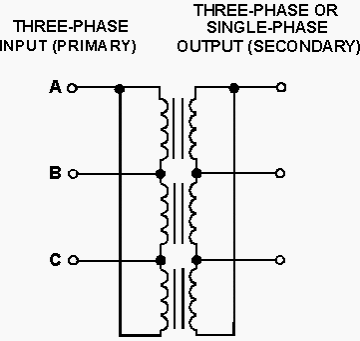
240v connections shown in blue 120v connections shown in red double delta connections always provide 240120v single phase t3. A schematic diagram of a three phase stator showing all the coils becomes complex and it is difficult to see what is actually happening. Three phase wiring diagrams always use wiring diagram supplied on motor nameplate colored leads are only applicable on the new rolled steel motor lines. Also in 3 phase the conductors need only be 75 the size of conductors for single. Three phase 3 line connection consist of three phase conductors and is employed only where there is no requirement for connecting phase to neutral loads. 3 phase power is typically 150 more efficient than single phase in the same power range.
1 hp x kva they also provide good performances under a single phase connection. Three phase alternators brush compound regulation 10kva 37kva 50hz 12kva 444kva 60hz. The power delivered to the load is the same at any instant. Three phase systems can be three phase three wire or three phase four wire systems. The generators of this 4 pole alternator series are three phase with brushes and they are characterised by a compound type regulation on the 3 phases. The latter can be connected in a star yn or delta d connection.
