This shows how to wire a network socket which is useful if you are wiring a home network. The complete ethernet pinout cable wiring reference with wiring step by step guide.

Wiring Diagram For Network Socket Wiring Diagram
Network socket diagram. Cat56 or 7 cable. Variety of cat6 socket wiring diagram. Each network diagram includes a description of the pros and cons of that particular layout as well as tips for building it. Remember the rj45 wiring order. The t 568b standard is the most commonly used. A wiring diagram is a streamlined standard pictorial depiction of an electrical circuit.
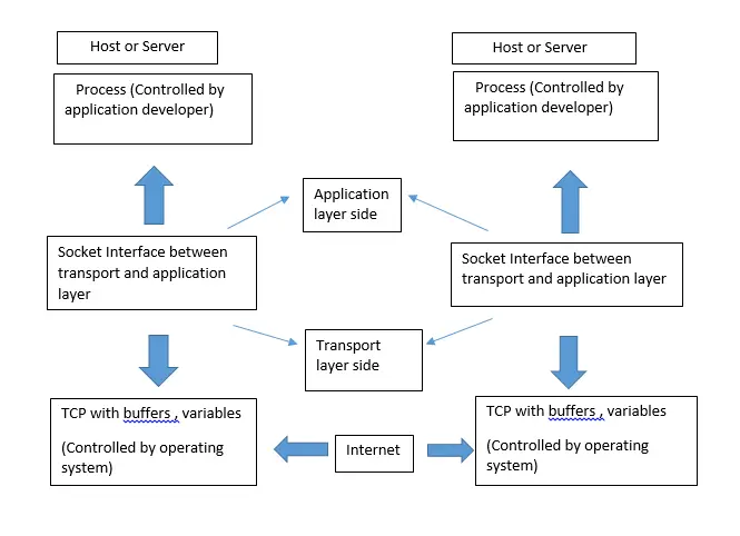
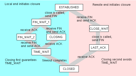
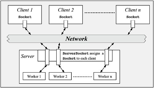
This means an application layer protocol is on one ip host connecting to an application layer. The wall jack may be wired in a different sequence because the wires may be crossed inside the jack. It contains well written well thought and well explained computer science and programming articles quizzes and practicecompetitive programmingcompany interview questions. A network socket is an internal endpoint for sending or receiving data within a node on a computer networkconcretely it is a representation of this endpoint in networking software protocol stack such as an entry in a table listing communication protocol destination status etc and is a form of system resourcethe term socket is analogous to physical female connectors communication. Click to check the right one for you or print as reference. Once a socket has been wired to each end of the network cable the final connection can be made using.
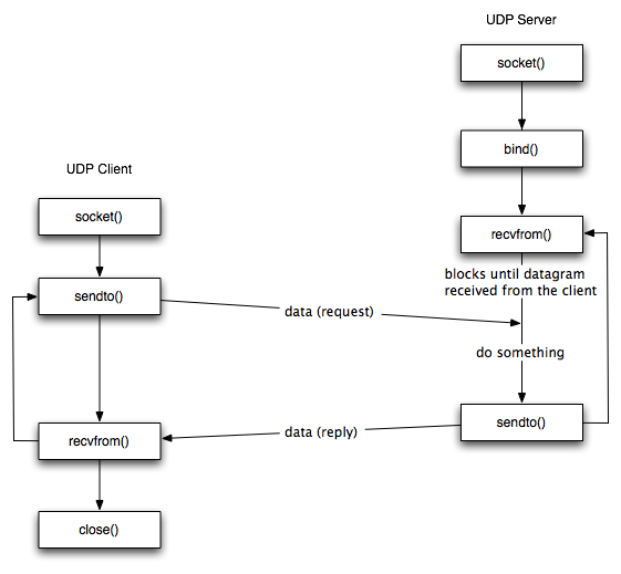
Click to find view print and more. This gallery contains network diagrams for wireless wired and hybrid home networks. Tcp and udp operate at the host to host layer in the ip communication model and provide host to host communication services for the application layer protocol. Next you need to make a list of what you will need. Networking tools for crimping cables. The wiring diagram is shown with the hook clip on the underside.
Rj45 pinout diagram shows wiring for standard t568b t568a and crossover cable. A network cable basically consists of a patch cable and two network connectors formally known as rj45 modular plugs attached to each of its ends. The jack should have a wiring diagram or designated pin numberscolors to match up to the color code below. Many home network layouts work fine but most are variations on a basic set of common designs. A computer science portal for geeks. Utp cable cat 56 or 7 termination sockets and connectors.
Cat 6 recommended will you use a patch panel. It reveals the parts of the circuit as streamlined shapes as well as the power and also signal links between the tools. To manage the connection between application layer network protocols tcp and udp use ports and sockets. What are the requirements for a home network. Ethernet switch or switches. The job of making your own cable is attaching.


