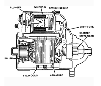
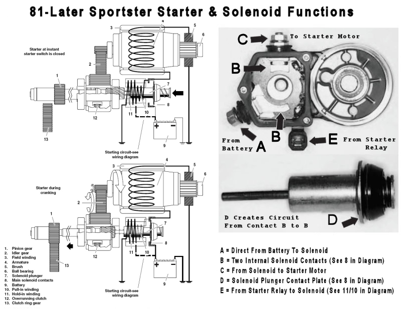
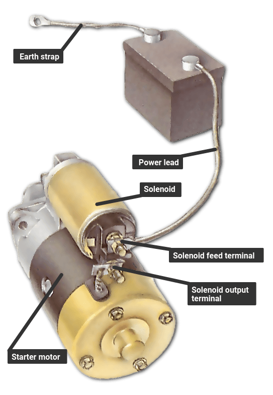
A typical starter solenoid has one small connector for the starter control wire the white connector in the photo and two large terminals. One for the positive battery cable and the other for the thick wire that powers the starter motor itself see the diagram below.

Pre Engaged Starter Motor Automobile
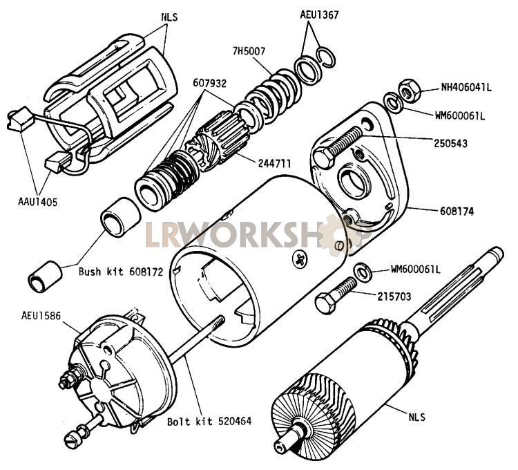
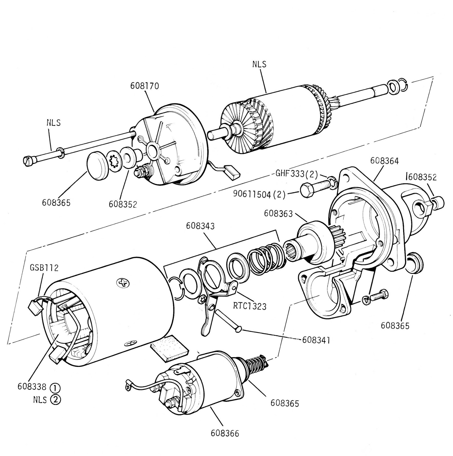
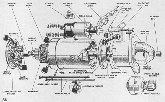
Starter motor diagram. Starter motor diagram the electric starter motor or cranking motor is the most common type used on gasoline engines and small diesel engines. The starter system is simple and the checks on it are straightforward. Electrical checks are made with a circuit tester or test lamp or with a voltmeter. 3ph starter3ph motor line voltage control three phase 3ph motor starter controlling a three phase motor rev 08 aug 2006 the above wiring diagram assumes your magnetic starter has a 240v coil. If the starter does not turn the engine although the car battery is in good condition the fault may be a simple mechanical one or it may be an electrical one in the starter motor circuit. If you have a 120v coil instead of running a line from coil overload l2 you must run coil overload neutral.
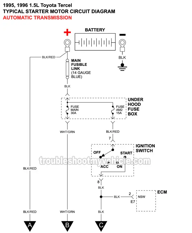
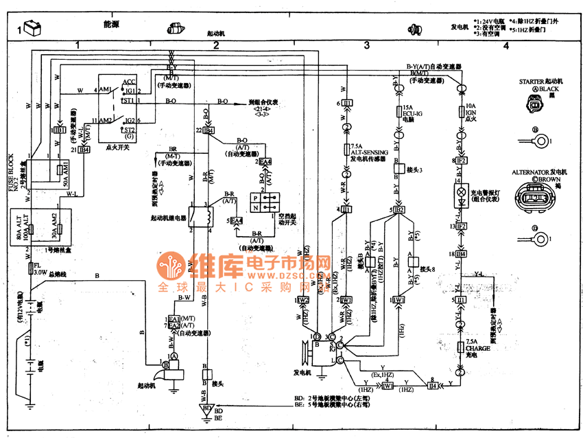
See how the anti. The security starter relay controlled car starter wiring diagram is as shown in the. To ensure that the starter can stall automatically and the starter circuit not connected after the engine starts some cars adopt the compound relay circuit with safety driving protection. Security starter relay controlled car starter wiring diagram. The modern starter motor is either a permanent magnet or a series parallel wound direct current electric motor with a starter solenoid similar to a relay mounted on it. A mechanical check to see if the starter pinion gear.
Learn to navigate this systems wiring circuitry and diagram using current flow analysis relay and module operation and neutral switch actuation such as circuit completion.

