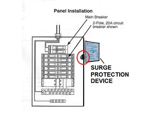
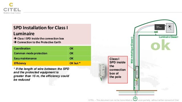
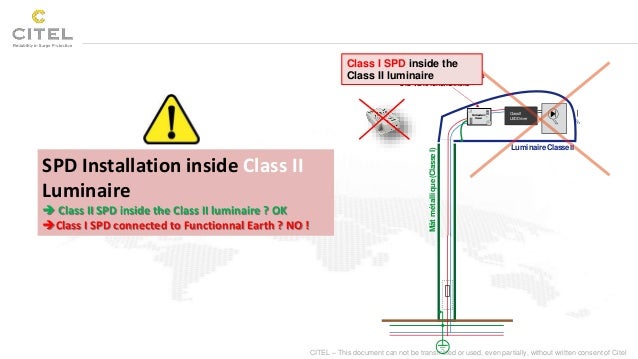
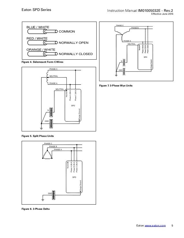
This device is connected in parallel on the power supply circuit of the loads that it has to protect see fig. The surge protection device spd is a component of the electrical installation protection system.

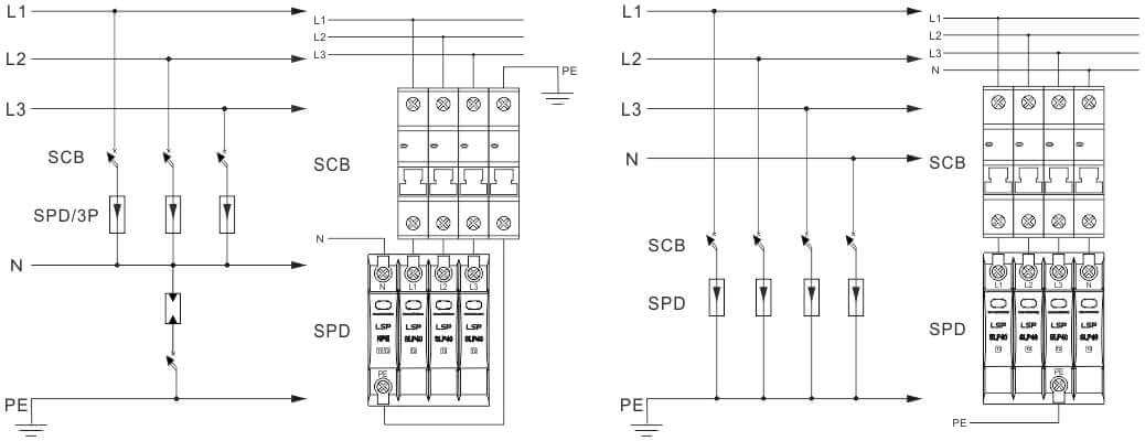
Two Types Of Spd Connections In A Tt Wiring System
Spd connection diagram. Connection leads should be cut to minimum possible length. The total length of the connection conductors is l l1l2l3. In class b c class section 16mm2 minimum we have to use a minimu. Board type b class and c class surge arresters must be connected in parallel to the system. J17it can also be used at all levels of the power supply network. Surge protective devices are designed to protect against transient surge conditions.
Accordingly a spd should be chosen with a voltage protection level up adapted to protection of the equipment see fig. For high frequency currents the impedance per unit length of this connection is approximately 1 µhm. Never coil or push aside excess length. Confirm that the spd is correctly rated for the system to which it is to be connected to. Confirm that the spd is correctly rated for the system to which it is to be connected to. Dc systems measure from positive and negative input.
Large single surge events such as lightning can reach hundreds of thousands of volts and can cause immediate or intermittent equipment failure. Measure l n l g l l and n g of the ac system. Measure l n l g l l and n g of the ac system. Connection leads should be cut to minimum possible length. Dc systems measure from positive and negative input. Never coil or push aside excess length.


