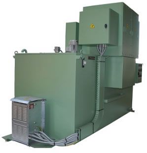
In order to start a slip ring motor the accelerating torque has to be sufficiently higher than the resisting torque. Find here slip ring starter slip ring motor starter manufacturers suppliers exporters in india.
Starting Methods Of Three Phase Induction Motors
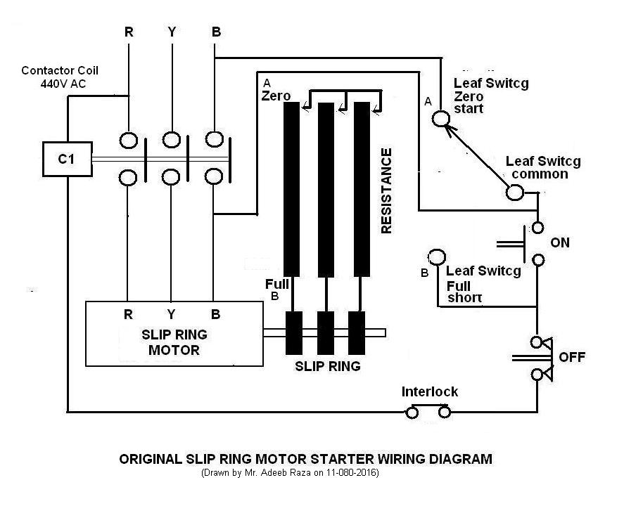
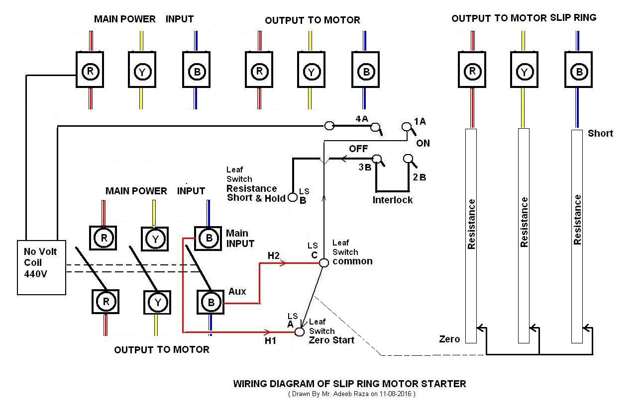
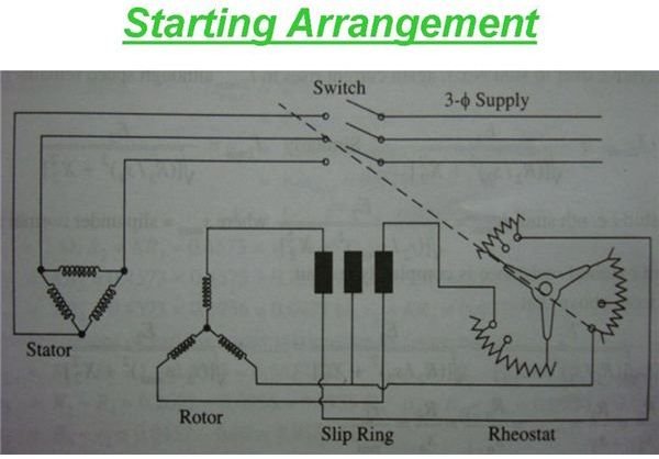
Slip ring motor starter diagram. A slip ring is an electromechanical device that allows the transmission of power and electrical signals from a stationary to a rotating structure. The rotor begins to rotate and the rotor resistances are gradually cut out as the speed of the motor increases. Slip ring induction motor study and speed control by variable. As the motor accelerates. When the motor is running at its rated full load speed the. Three phase slip ring rotor starter control power diagrams two speeds one direction three phase motor connection power and control diagrams two speeds two directions multispeed 3 phase motor power control diagrams.
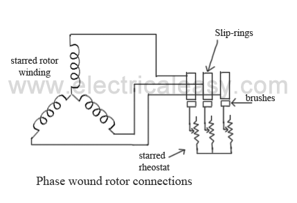
Why using a starter for slip ring motors. A slip ring can be used in any electromechanical system that requires rotation while transmitting power or signals. The slip ring induction motor has two distinctly separate parts one is the stator and other is the rotor. Rotor resistance starter in three phase induction motor electrical academy. Get contact details address of companies manufacturing and supplying slip ring starter slip ring motor starter across india. A wound rotor motor also known as slip ring rotor motor is a type of induction motor where the rotor windings are connected through slip rings to external resistance.
Adjusting the resistance allows control of the speedtorque characteristic of the motor. It can improve mechanical performance simplify system operation and eliminate damage prone wires dangling from movable joints. Three phase motor control installation wiring diagrams. Wound rotor motors can be started with low inrush current by inserting high resistance into the rotor circuit. Check more diagrams here. In this video you will learn connection of slip ring motor with starter panel serenity by audionautix is licensed under a creative commons attribution licenc.
Full starting resistance is connected and thus the supply current to the stator is reduced. Three phase slip ring rotor starter control diagram control diagram. Higher is the inertia higher has to be the accelerating torque otherwise the start will be very long and the motor can be damaged by the heating. Overhead crane or eot crane power diagram. The stator circuit is rated as same in the squirrel cage motor but the rotor is rated in frame voltage or short circuit current. The frame voltage is the open circuit voltage when the rotor is not rotating and gives the measure of turns.
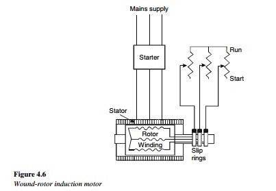
The connection diagram of the slip ring starter induction motor is shown below.


