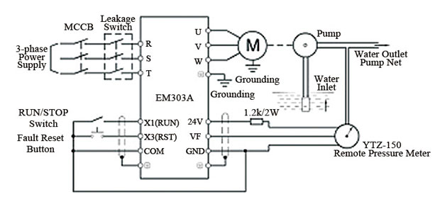
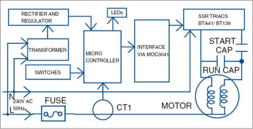
May 31 2018 single phase submersible pump starter wiring diagram on water control panel inside to. Single phase wiring diagrams single phase wiring diagram for 05hp pumps with governor switch single phase wiring diagram with governor switch single phase wiring diagram without governor switch three phase wiring diagrams three phase 208v wiring diagram three phase 230v wiring diagram three phase 460v wiring diagram three phase 575v wiring diagram kb pump wiring diagrams kb pump 230v wiring.

Bl 2674 Domestic Pump Control Panel Wiring Diagram
Single phase water pump control panel wiring diagram. 3 phase submersible pump control panel circuit diagram 3 phase submersible pump wiring diagram single phase water pump motor wiring diagram how to connect submersible pump wires. The control circuit wiring could then be wired to a single switch located at a remote location. Plug in ready wiring makes installation. Single phase submersible pump starter wiring diagram gallery amazing single phase water pump control panel wiring diagram frieze. I hope after watching the above single phase submersible pump starter wiring diagram guide video tutorial i hope now you will fully understood the complete submersible pump control starter wiring diagram or installation and now you will be able to wire or make your own submersible pump motor starter however now if you have any question regarding the video tutorial or diagram then you can ask. Jun 19 2017 single phase 3 wire submersible pump control box wiring diagram or single phase submersible pump starter wiring diagram and wiring installation guide.
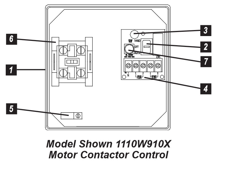
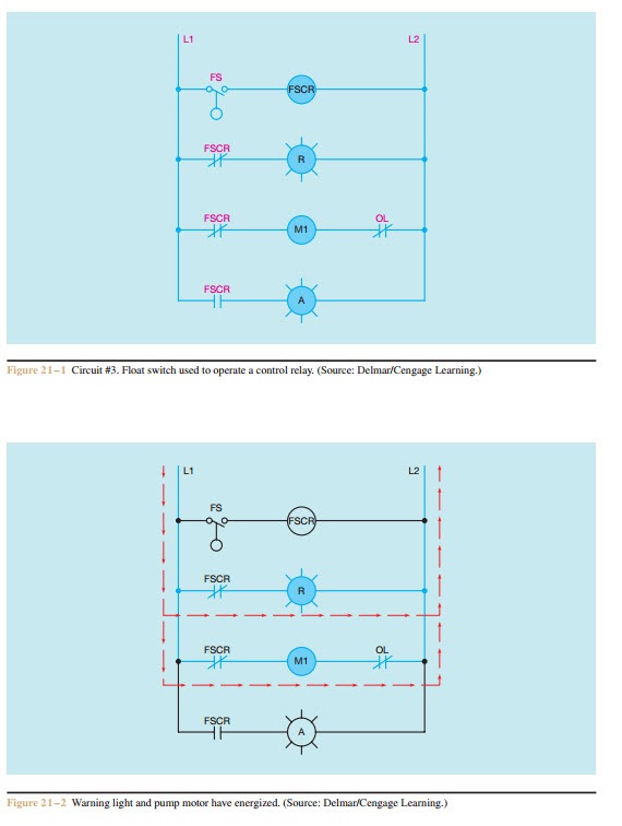
29 best submersible pump images on pinterest. Controlling a simplex one pump system in a water or sewage installation. In which i control a three phase submersible pump motor using magnetic contactor. Sim a single phase simplex sump pump control panel hoa switch for manual pump control and green led pump run light. 3 wire submersible pump wiring diagram wellread. Single phase motors are used to power everything from fans to shop tools to air conditioners.
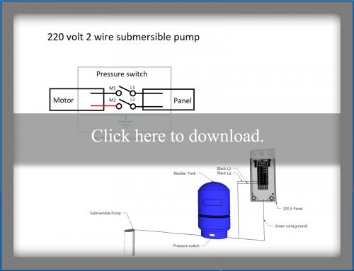
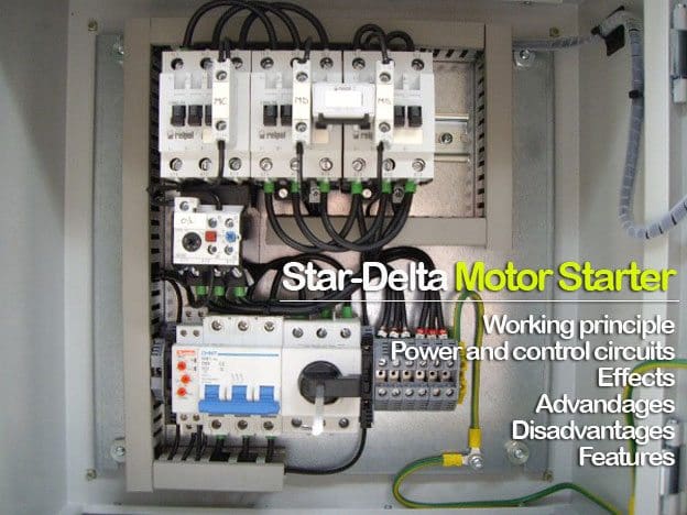
Not only a contactor but also i install the thermal overload relay which will protect the motor form burning in case of over current flow to the circuit. Residential power is usually in the form of 110 to 120 volts or 220 to 240 volts. A low voltage control circuit would be required which could be wired into the 240 volt pump circuit wiring and the control circuit will need to have over current protection. 3 phase submersible pump wiring diagram. Wiring a motor for 230 volts is the same as wiring for 220 or 240 volts. Single phase submersible motor starter wiring diagram explanation.
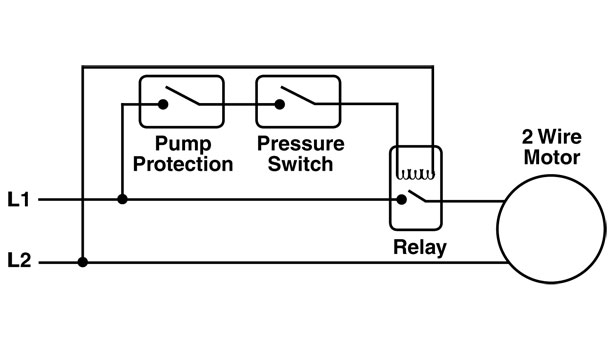
A relay contactor may also be used to control a pump motor. Control board with power on and. Some motors allow both 120 volt and 240 volt wiring by providing a combination of wires for doing so.

