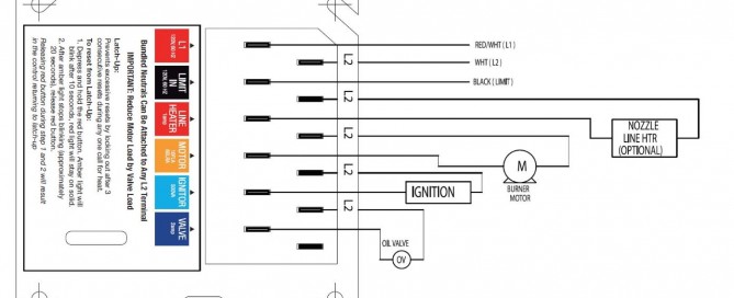
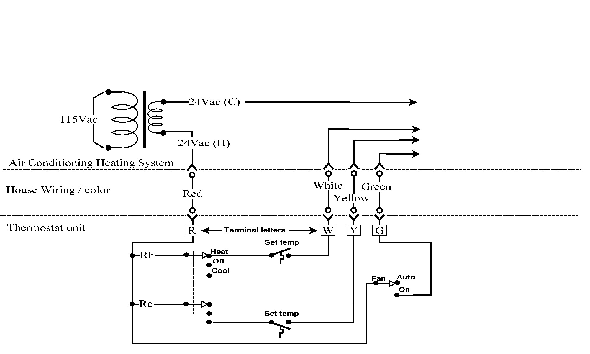
Furthermore this thermostat wiring diagram is specifically for a system with two transformers. Fig6 is a typical installation diagram for a residential cooling system.
Typical Security Lighting Wiring Diagrams H1 Wiring Diagram
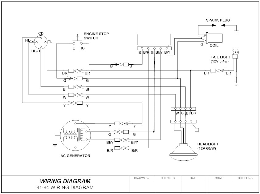
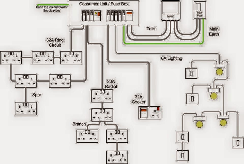
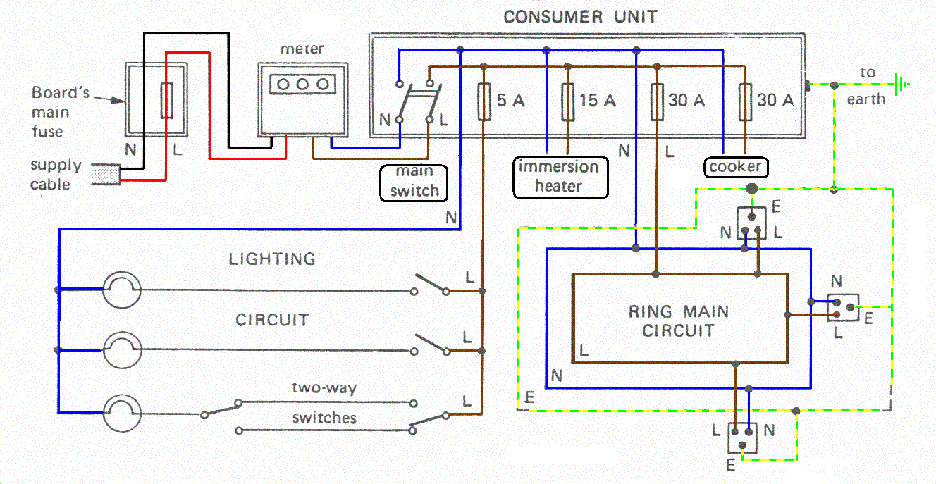
Typical residential wiring diagram. Oct 22 2016 4 best images of residential wiring diagrams house electrical. Unlike a photographic diagram a wiring diagram utilizes abstract or streamlined shapes and lines to reveal parts. It normally shows only what the terminal board connections are and very rarely will it include any internal wiring of the unit. Many home network layouts work fine but most are variations on a basic set of common designs. Oct 22 2016 4 best images of residential wiring diagrams house electrical. The home electrical wiring diagrams start from this main plan of an actual home which was recently wired and is in the final stages.
The home electrical wiring diagrams start from this main plan of an actual home which was recently wired and is in the final stages. Your system likely only has one transformer as most typical residential. Three way switch wiring diagram 3 way power into light light between 3 way switches 3 way switch wiring. If you have a two stage heat pump then you will also utilize terminal y2 for the second stage. Fantazs laipa home electricity. This page takes you on a tour of the circuit.
Depending on your screen size. This diagram is used primarily by the installing contractor. Each network diagram includes a description of the pros and cons of that particular layout as well as tips for building it. The important components of typical home electrical wiring including code information and optional circuit considerations are explained as we look at each area of the home as it is being wired. That is a basic honeywell thermostat wiring diagram for a single stage heat pump. Romex is a common type of residential wiring that is categorized by the national electrical code nec as underground feeder uf or non metallic sheathed cable nm and nmc.
The coating on nmc cable is non conducting flame resistant and moisture resistant. B legend factory power wiring factory control wiring field control wiring field power wiring component connection field splice junction contactor capacitor dual run crankcase heater. The important components of typical home electrical wiring including code information and optional circuit considerations are explained as we look at each area of the home as it is being wired. Just how is a wiring diagram different from a photographic diagram. Photographic representations are usually images with labels or highly detailed illustrations of the physical parts. Connection diagram g 13 equip gnd l1 11 21 ch comp cont 23 ofm cap l3 schematic diagram ladder form may be factory or field installed 319390 401 rev.
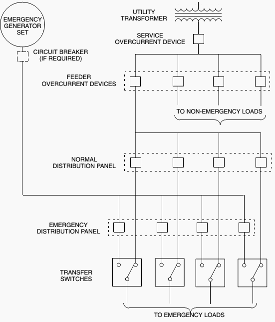
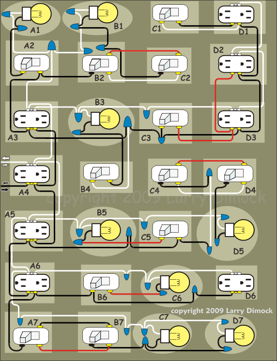
Or canadian circuit showing examples of connections in electrical boxes and at the devices mounted in them. The image below is a house wiring diagram of a typical us. This gallery contains network diagrams for wireless wired and hybrid home networks. Nm and nmc conductors are composed of two or more insulated conductors contained in a non metallic sheath.
