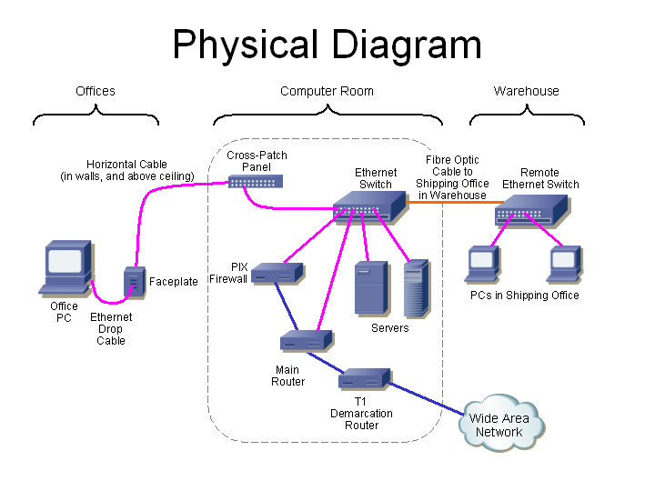
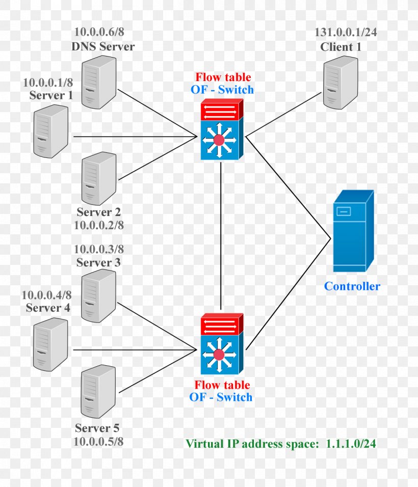
This gallery contains network diagrams for wireless wired and hybrid home networks. Circuit switching is a connection oriented network switching technique.
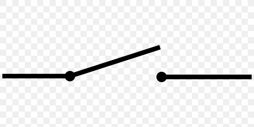
Electronic Symbol Electrical Network Electrical Switches
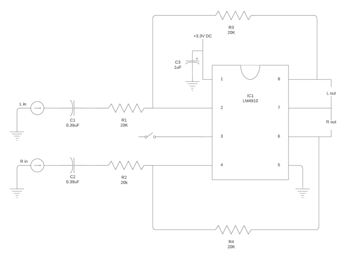
Network switch circuit diagram. Feb 5 2020 explore elects agass board electrical diagram on pinterest. Multiple light wiring diagram. The dedicated pathcircuit established between sender and receiver provides a guaranteed data rate. A network switch is a piece of hardware that facilitates communication between computers on an internal network. Resistors 100 ω r1 560 ω r2 46 kω r3 18 kω 3 r4 33 kω r5. The public switched telephone network datakit b channel of isdn optical mesh network etc are some of the examples of circuit switched networks.
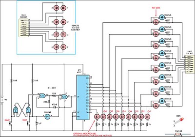
A resistor is an electronic component which opposes the flow of current or prevents. Here a dedicated route is established between the source and the destination and the entire message is transferred through it. The hot and neutral terminals on each fixture are spliced with a pigtail to the circuit wires which then continue on to the next light. Phases of circuit switch connection. Without the switching function the devices could talk through the router to the greater internet but not to each othersomething as simple as copying an mp3 from your laptop to your desktop over the network would be impossible. 555 ic ic 1.
A relay is a switching device which is used to switch the circuit on when required and turn off whenever required. In circuit switching network resources bandwidth is divided into pieces and bit delay is constant during a connection. The source is at sw1 and 2 wire cable runs from there to the fixtures. Circuit switching is a method of implementing a telecommunications network in which two network nodes establish a dedicated communications channel through the network before the nodes may communicatethe circuit guarantees the full bandwidth of the channel and remains connected for the duration of the communication sessionthe circuit functions as if the nodes were physically connected as with. Cd 4017 ic ic2. Circuit switching diagram in this type of switching there is a set of switches connected with physical links.
Data can be transmitted without any delays once the circuit is established. Many home network layouts work fine but most are variations on a basic set of common designs. The main components of the circuit are. See more ideas about electrical diagram electrical circuit diagram electrical engineering. Each network diagram includes a description of the pros and cons of that particular layout as well as tips for building it. This diagram illustrates wiring for one switch to control 2 or more lights.

