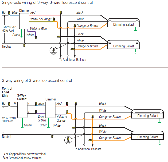
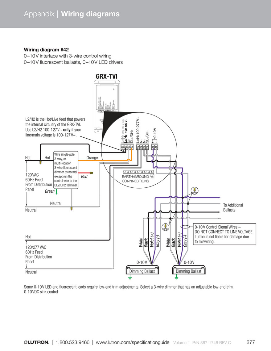
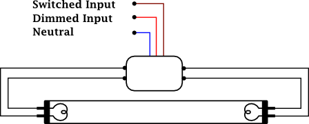
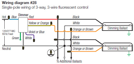
Dimming fluorescent lights are usually found in commercial and institutional environments and not common in the household. It shows the elements of the circuit as simplified shapes and also the power and also signal connections in between the devices.
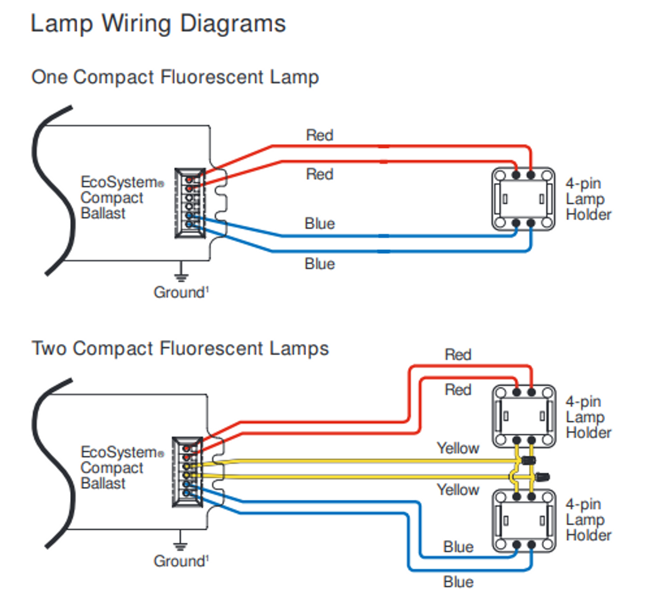
Fluorescent With Dimmer Wiring Diagram Kedurang Source
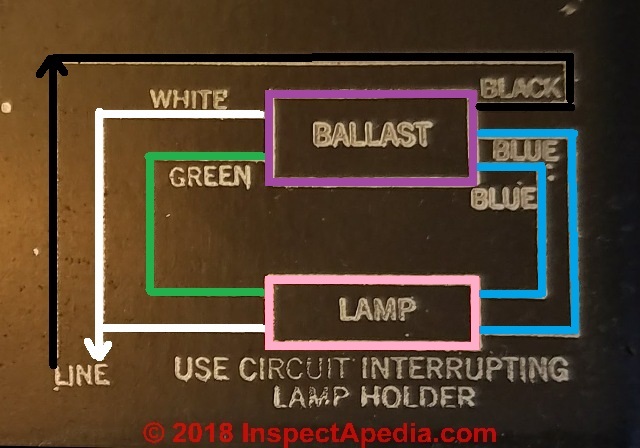
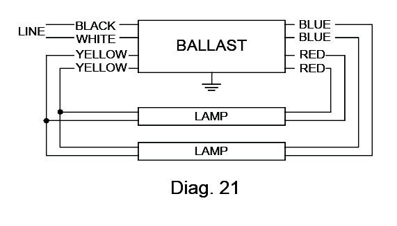
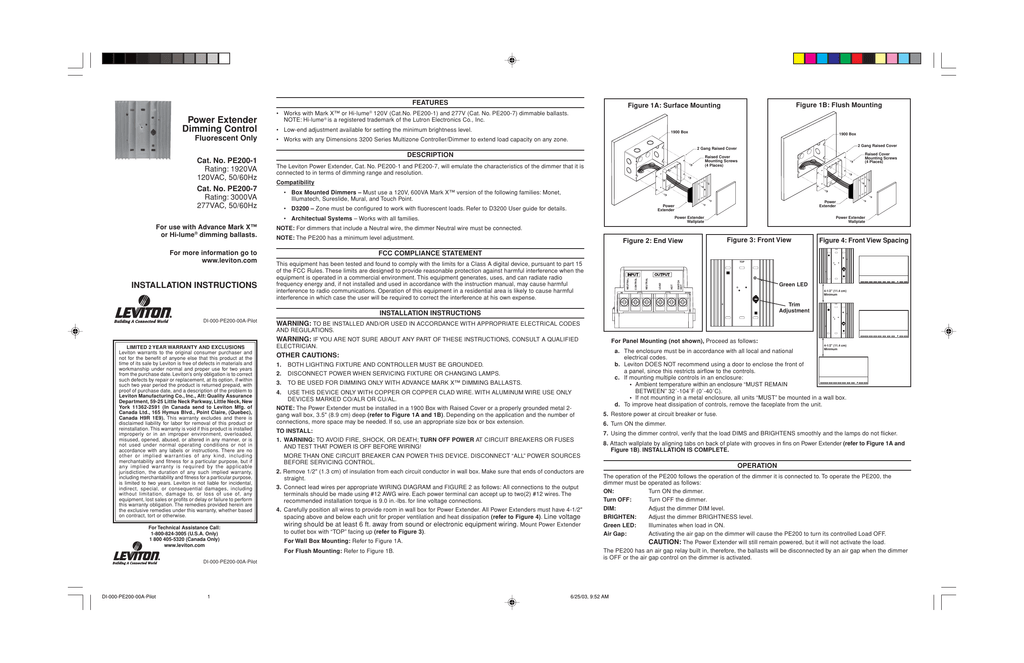
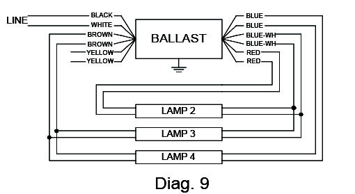
Fluorescent dimming ballast wiring diagram. Fluorescent ballast wiring diagram 8 foot fluorescent ballast wiring diagram advance fluorescent ballast wiring diagram compact fluorescent ballast wiring diagram every electric arrangement is composed of various diverse pieces. Selecting cbf lutron enables customers to order ballasts with a custom ballast factor cbf. Otherwise the structure wont function as it ought to be. Parallel ballasts can only be wired in parallel according to the diagram on the ballast. What can be intimidating is the plethora of wiring diagrams on the new ballast none of which matches exactly the wiring diagram on the original unit. Ballast wiring mounting isgrounded bythespecifiedterminalor a blockson theballastaccept following wire gauges.
High ballast factor 118 to low 71 step dimming 100 light level of a 2 high ballast factor is approximately the same as a 3 lamp normal ballast factor 100 light level of a 3 high ballast factor is approximately the same as a 4 lamp normal ballast factor multi volt 120 277v flexibility. Power wiring and ecosystem bus. Ballast manufacturers like phillips offer technical support including a telephone number to call for assistance. Dimming ballasts are available for fluorescent tubes and cfls that use an external ballast. In concept replacing a fluorescent lamp ballast or transformer is pretty simple. Variety of 0 10v dimming ballast wiring diagram.
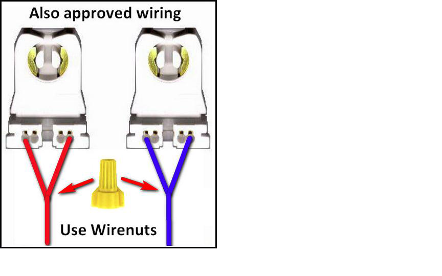
Changing the wiring on a fluorescent light fixture from series to parallel involves changing the ballast from a series to a compatible parallel ballast. One 18 awg or 16 awg 075 mm or 15 mm2 solid per terminal ballast mounts using two mounting tabs or studs within a fluorescent fixture. See ballast specification sheet for available ballast factors for a given lamp. Each component ought to be placed and connected with different parts in particular manner. These ballasts are usually rapid start or programmed start and have a good dimming range. The ballast factor of lutron linear fluorescent dimming ballasts is 085 or greater and for compact fluorescent dimming ballasts it is 095 or greater.
One 18 awg or 075mm2 2solidperterminal lamp 2wiring. A wiring diagram is a streamlined standard photographic representation of an electric circuit. Series ballasts can only be wired in series according to the diagram on the ballast.
