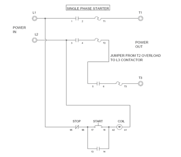
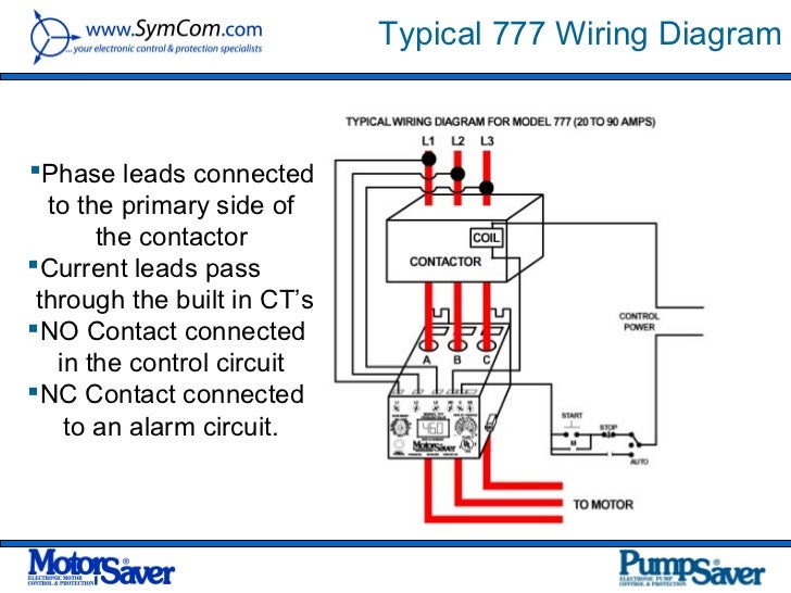
Home about us news wiring a single phase motor through a 3 phase contactor. Properly connect a single phase motors to a three phase starter.

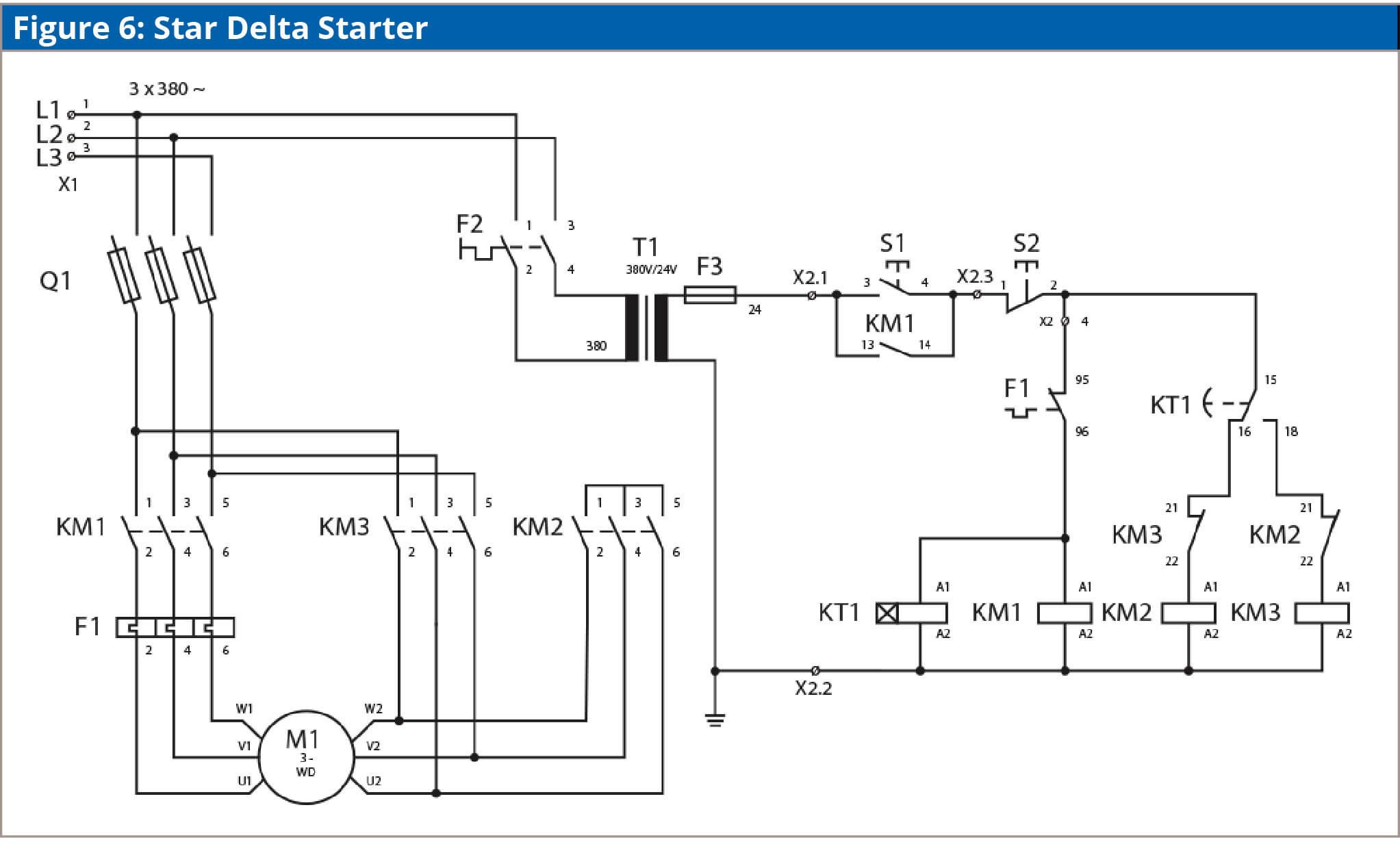
Delta Wiring Schematic C3 Wiring Diagram
Single phase starter wiring connection. A wiring diagram is a simplified standard pictorial depiction of an electrical circuit. Single phase motors are used to power everything from fans to shop tools to air conditioners. It reveals the parts of the circuit as simplified shapes and the power and signal links between the gadgets. Assortment of single phase submersible pump starter wiring diagram. This video will show you how to connect a single phase motor with two capacitors. Wiring a single phase motor through a 3 phase contactor.
Merely ignore the control wiring in red 3ph starter1ph motor line voltage control three phase 3ph motor starter controlling a single phase motor rev 08 aug 2006 some 3 phase magnetic motor starters require current to be seen across each of the three overloads. A motor with a start and run capacitor and a start and run coil. Residential power is usually in the form of 110 to 120 volts or 220 to 240 volts. Each component ought to be placed and linked to different parts in particular manner. Posted january 18 2018 by springercontrols. Wiring a motor for 230 volts is the same as wiring for 220 or 240 volts.
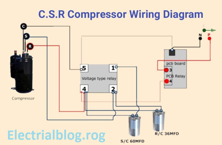
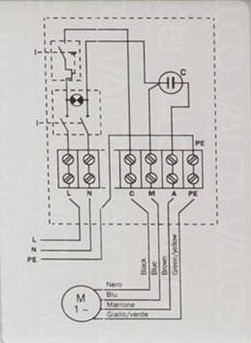
Single phase motor wiring diagram with capacitor baldor single phase motor wiring diagram with capacitor single phase fan motor wiring diagram with capacitor single phase motor connection diagram with capacitor every electrical arrangement is made up of various unique pieces. Types of single phase induction motors electrical a2z single phase induction motors are traditionally used in residential applications such as ceiling fans air conditioners washing machines and refrigerators single phase motor wiring with contactor diagram the plete guide of single phase motor wiring with circuit breaker and contactor diagram. The above diagram is a complete method of single phase motor wiring with circuit breaker and contactor. Some motors allow both 120 volt and 240 volt wiring by providing a combination of wires for doing so. Single phase power is typically reserved for lower power requirements however in some cases powering a small motor with single phase input power is practical. Single phase motor wiring diagram with capacitor start.
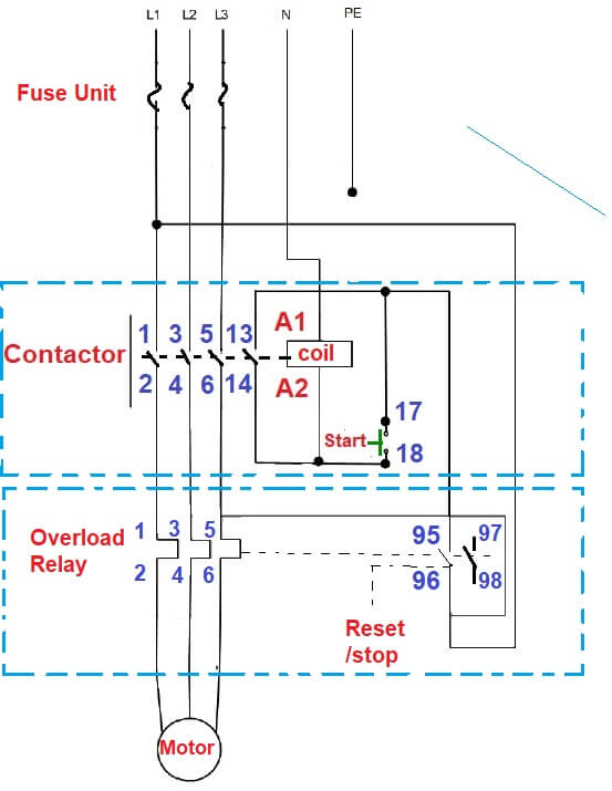
A wiring diagram is a simplified traditional photographic representation of an electric circuit. Collection of single phase motor starter wiring diagram. In the above one phase motor wiring i first connect a 2 pole circuit breaker and after that i connect the supply to motor starter and then i do cont actor coil wiring with normally close push button switch and normally open push button switch and in last i do connection between capacitor. It reveals the elements of the circuit as streamlined forms and also the power and signal links in between the gadgets.
