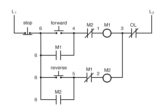
Start stop control wiring diagrams single station with motor stopped pilot light l1 start l2 i 1 stop 2 oi 3 n wol. C i m nc.

Start Stop Wiring Diagram 3 Phase With Contactor
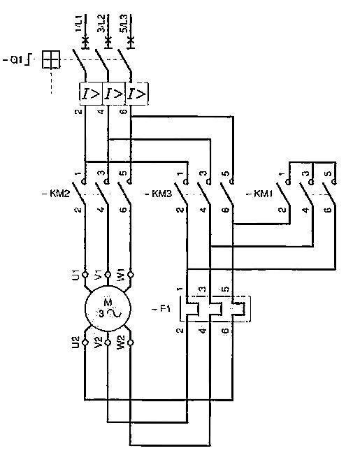
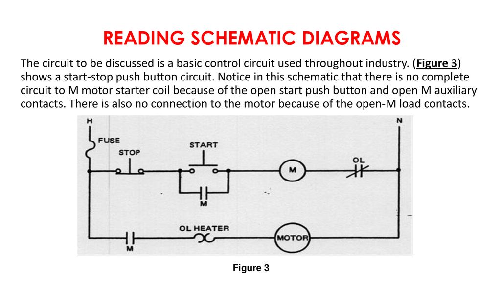
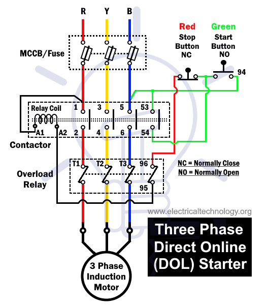
Motor starter wiring diagram start stop. See image below for an example of 3 wire control being used to pull in a contactor to start a 3 phase motor. The most common use of 3 wire control is a startstop control. This video is a step by step explanation of wiring start stop basics. Push to make ptm switch use to start the motor and push to brake ptb switch use to stop the motor. The seal in contact is now maintaining power to the coil overriding the start pushbutton and it is no longer needed to be held down. A motor starter is a combination of devices used to start run and stop an ac induction motor based on commands from an operator or a controller.
Pressing start immediately sends power through the start pushbutton and the seal in contacting energizing the coil. With the motor stopped. How to wire a motor starter libraryautomationdirect throughout motor starter wiring diagram start stop image size 576 x 511 px and to view image details please click the image. Improper wiring can kill injure start fires burn out motors or anyall of the above. Here is a picture gallery about motor starter wiring diagram start stop complete with the description of the image please find the image you need. I describe each of the components involved such as the motor starter overload start pushbutton stop pushbutton and control power and.
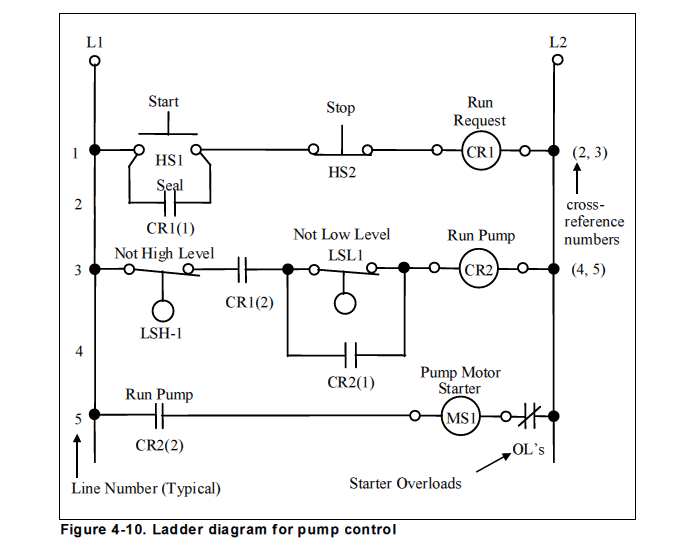
T w 6. Pilot light l2 4 2 3 pilot light start stop bulletin 1495 normally closed auxiliary contacts are required. 3ph starter3ph motor line voltage control three phase 3ph motor starter controlling a three phase motor rev 08 aug 2006 the above wiring diagram assumes your magnetic starter has a 240v coil. Wiring diagram for a starter controlling a 480v motor with 120v startstop button of course the coil voltage must be and the motor can be whatever voltage this with a plc output straight to a starter and get rid of the startstop switch. When you press the start button and the stop button is not pressed the 24vdc relay energizes and it pulls in the r1 contactor that feeds three phase power to the motor. Wiring diagram single motor with start stop switch basic control motor to get start or stop the motor use a push button switch as a trigger a motor.
The coil of the motor starter can be de energized several ways. In this video i demonstrate a 3 wire startstop circuit. As long as you follow the ladder diagram and take it one wire at a time its simple. This is the first of many motor control. In north america an induction motor will typically operate at 230v or 460v 3 phase 60 hz and has a control voltage of 115 vac or 24 vdc. With the motor running contacts are open.


